


Chapter 10 Wiring the modules 161
Installation and Maintenance Guide
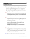
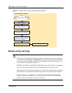
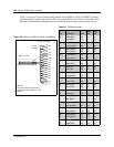
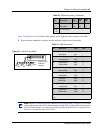
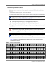
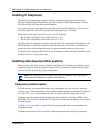
Table 33 and Figure 57 provide the wiring scheme for the eight pairs that connect to the ASM.
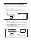
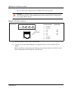
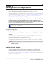
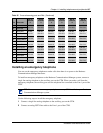
3 Plug the female amphenol connector into the interface on the front of the module.
41 Yellow-Blue X16 16 32
16 Blue-Yellow X16 16 32
42-40
17-25
no connections
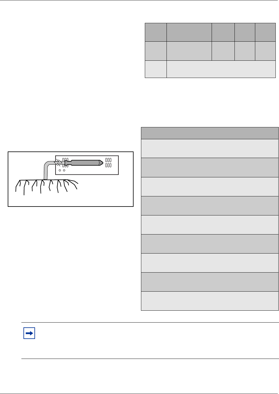
Table 33 ASM wiring chart
Pin Wire color Port Set
Figure 57 Wiring for an ASM 8
26 White-Blue X01 1
1 Blue-White X01 1
27 White-Orange X02 2
2 Orange-White X02 2
28 White-Green X03 3
3 Green-White X03 3
29 White-Brown X04 4
4 Brown-White X04 4
30 White-Slate X05 5
5 Slate-White X05 5
31 Red-Blue X06 6
6 Blue-Red X06 6
32 Red-Orange X07 7
7 Orange-Red X07 7
33 Red-Green X08 8
8 Green-Red X08 8
34-50 no connection
9-25
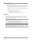
Note: Refer to “Line and extension numbers for specific modules” on page 121 to see the
relationship between the DS30 channel number and the DNs. Configuration information is
included in the chapters on setting up modules and DNs in the Business Communications
Manager Programming Operations Guide.
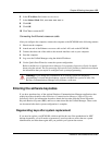
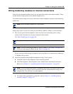
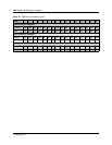
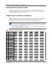
Table 32 DSM wiring chart (Continued)
Pin Wire color Port
Sets
1st
Sets
2nd
8R
33T
32T
7R
31T
6R
30T
5R
29T
4R
28T
3R
27T
2R
26T
1R
25-pair female
amphenol
connector