


178 Chapter 12 Installing the Companion system
P0993298 02
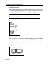
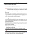
RPI output connections
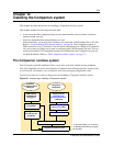
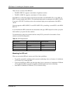
Feed the output pairs in through the bottom of the RPI and route the pairs to the output connectors.
Figure 64 shows how to route the output pairs. If you use one pair to power a base station, connect
the power pair to -PWR(1) and +PWR(1). If you use two pairs to power a base station, connect one
pair to -PWR(1) and +PWR(1), and the second pair to -PWR(2) and +PWR(2).
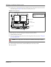
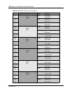
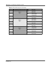
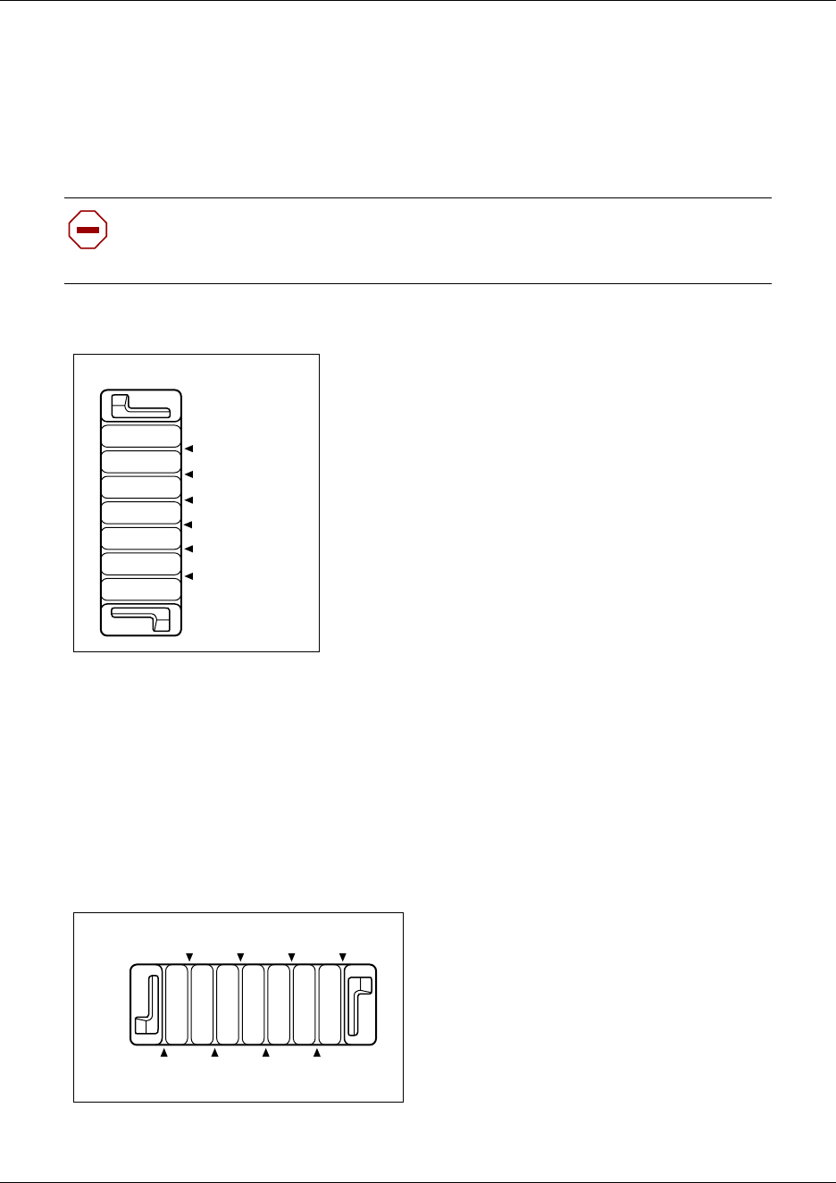
Figure 64 Output connector pinout
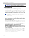
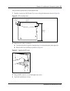
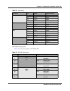
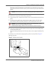
RPI input connections
Feed the TCM input pairs from the Business Communications Manager distribution frame through
the top of the RPI and route them to the input connectors (IBIX1 to IBIX4).
Figure 65 shows how to route the input pairs. The maximum number of input pairs in an RPI
installation is 16. Table 38 lists the pinout and signal references.
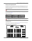
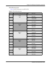
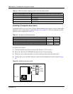
Figure 65 Input connector pinout
Caution: Ensure both pairs have the same polarity.
If you connect two power pairs with opposite polarities, you can damage the base
station and RPI.
OBIXn
-PWR(1)
TCM
TCM
+PWR(1)
-PWR(2)
+PWR(2)
OBIXn
-PWR(1)
-PWR(2)
TCM
TCM
+PWR(1)
+PWR(2)
IBIXn
Pin 3 Pin 1
Pin 2Pin 4Pin 6Pin 8
Pin 5Pin 7
Pin 7
IBIXn
Pin 5 Pin 3 Pin 1
Pin 8Pin 6Pin 4Pin 2