


118 Chapter 7 Setting media bay module DIP switches
P0993298 02
Determining module DIP switch settings
After you determine in which order you want to assign the modules, you determine the specific
switch settings for each module.
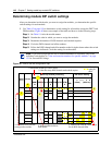
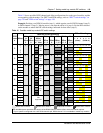
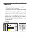
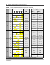
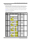
1 Use Table 15 on page 119 to determine a switch setting for all modules except the DECT and
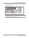
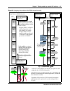
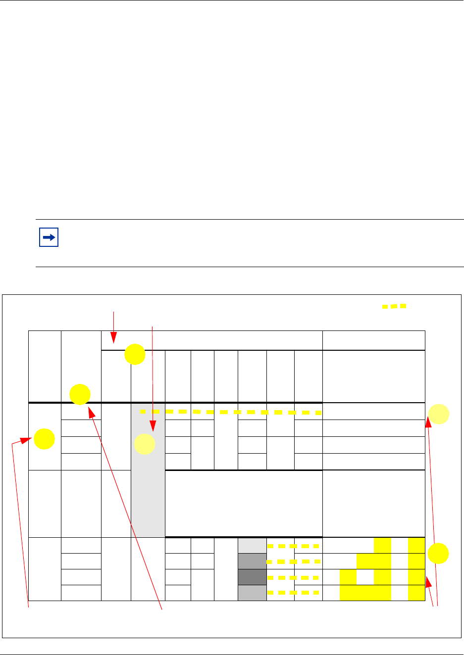
FEM modules. Figure 40 shows an example of the table and how to do the following steps:
Step 1: On Table 15 circle the module names.
Step 2: Number the order in which you want to assign the modules.
Step 3: Determine the number of DS30 channels each module requires.
Step 4: Circle the DS30 channel and offset numbers.
Step 5: Follow the DS30 channel and offset number to the far right column where the switch
settings are indicated. Circle the setting for each module.
Figure 40 How to use the configuration map
Note: If you must assign specific line or extension numbers to a module, refer to the
individual switch tables in “Line and extension numbers for specific modules” on page
121 for line and DN listings.
DS30
ch. #
Off-set
Media bay module positioning DIP switch setting
DSM
16
DSM 32 4x16 ASM
8
DTM CTM CTM
8
BRI
123
(offset)
456
(DS30 ch)
2
0
on on on on on on
7 0 on on on off on off
1 on on off off on off
2 on off on off on off
3 on off off off on off
1. Indicate the modules you want to install
2. Note how many DS30 channels each module requires
3. Choose the DS30 channels
to assign to the modules
4. Assign an offset number to
each module
5. Make a note of the DIP switch settings
for the DS30 channel/offset
1
2
3
4
5
5
DIP switch
setting for
offset