


134 Chapter 8 Installing media bay modules
P0993298 02
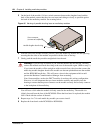
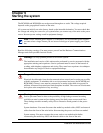
5 On the back of the module, if it has a wired connector between the daughter board and the
back of the module, ensure that the wires are intact and sitting as closely as possible against
the back of the media bay module. See warning below.
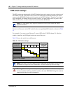
Figure 45 Warning of possible shorting issue on media bay modules
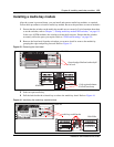
6 With the face of the module towards yourself, insert the media bay module into the open bay,
ensuring that the sides of the module are parallel with the sides of the bay.
7 Gently push the media bay module straight back into the unit.
You will hear a click when the module is firmly seated in the media bay. The module sits
slightly forward from the face of the BCM1000. When the front bezel is replaced, the module
face is flush with the surface of the unit.
8 Repeat steps 4 to 7 for each media bay module you want to install.
9 Replace the front bezel on the BCM1000 or BCM1000e.
Warning: If you feel any resistance as you slide the module into the housing, carefully
remove the module and check the wiring at the rear of the module again. (Refer to step 5.)
If you insert the modules off the straight or with too much force, the wires that connect the
media bay module daughter board to the module can become pinched between the module
and the BCM1000 media bay . This will cause a short in the equipment which would
prevent the Business Communications Manager from restarting.
Note: Some modules, such as the DECT module, do not have this wiring configuration.
However, it is still important that you insert modules carefully and squarely into the
housing to ensure that the power connector on the module correctly and securely connects
to the backplane of the media bay.
Module daughter board wiring.
Power connector
(connects to backplane)