


74 Chapter 2 Telephony hardware
P0993298 02
Digital Trunk media bay module
The Digital Trunk media bay module (DTM) connects a standard digital PSTN line to the Business
Communications Manager using either a digital or PRI line.
• On North American Business Communications Manager systems, the DTM connects to a T1
or PRI line. With a T1 line, you can add a maximum of 24 digital telephone lines. With a PRI
line, you can add a maximum of 23 digital telephone lines.
• On International Business Communications Manager systems, the DTM connects to an ETSI
or PRI digital line. With an ETSI or PRI line, you can add a maximum of 30 digital telephone
lines.
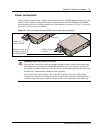
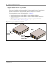
The front bezel of the DTM has a RJ48C connector that connects the DTM to the service provider
connection point. The faceplate also has a set of loopback connectors you can use to run loopback
tests. For details on loopback tests, refer to the Business Communications Manager Programming
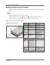
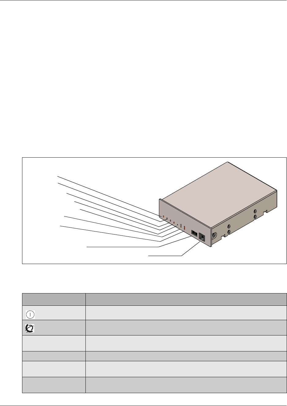
Operations Guide. Figure 18 shows the front of the module.
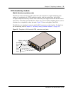
Figure 18 DTM module LEDs and connectors, front view
Table 8 provides a description of the function for each DTM LEDs.
Table 8 DTM LED functions
LED label Function
(Power) On indicates that the DTM is receiving +5 volts.
(Status) On indicates there is data communication between the DTM and the MSC card.
In Service Flashing indicates that the T1, ETSI or PRI trunks are out of service because a
loopback test is running or the DTM is initializing.
Loopback On indicates a continuity loopback test is running.
Receive Alarm On indicates a problem with the received digital transmission. This half-duplex link
does not work.
Receive Error On indicates a small error as a result of degraded digital transmission. Possible
causes are an ohmic connection, water ingress, or too long a loop.
Power LED
Status LED
In Service LED
Loopback Test LED
Continuity Loopback
Receive LEDs
Transmit LEDs
Loopback
RJ48C digital telephone line connector
Front view