


256 Chapter 19 Replacing a power supply
P0993298 02
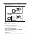
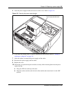
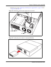
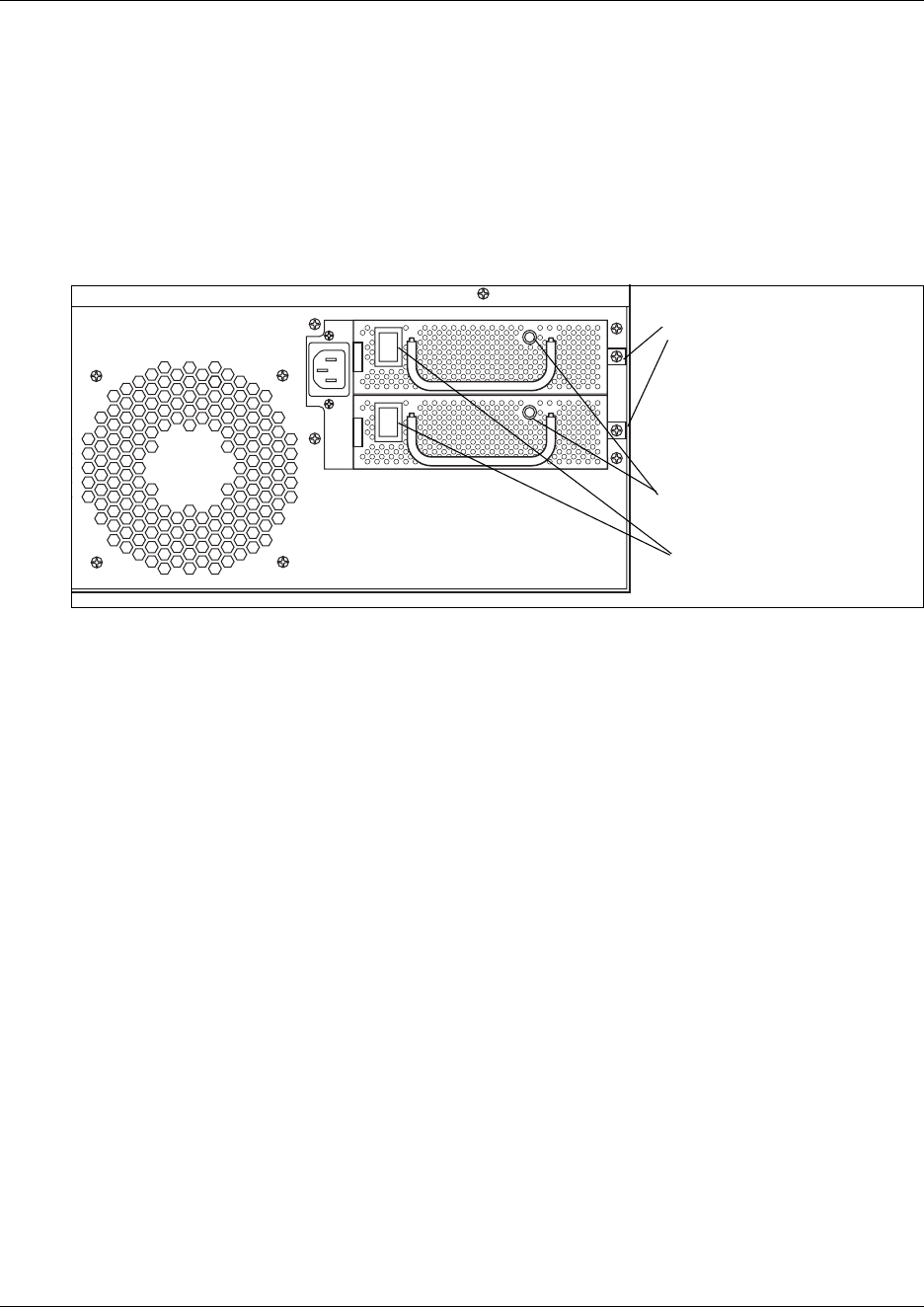
11 Insert the power modules into the redundant power supply housing at the back of the server.
a The face of the module is flush with the casing. You hear a click when it is properly
seated.
b Secure each module with a screw through the tab on the right side of the module.
These holes align with the middle two holes on the right of the power supply housing.
Refer to Figure 126.
Figure 126 Insert and attach the modules
12 Turn on the switches for both power modules.
13 Restore the units to operation as described in “Restarting the system” on page 220.
The Business Communications Manager system starts up when you connect the ac power
cord. System recovery takes several minutes to complete.
The LEDs on the power supply are on when the ac power is connected.
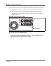
Module screws.
Rocker switches
Power module status LED