


158 Chapter 10 Wiring the modules
P0993298 02
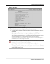
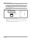
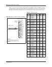
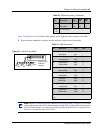
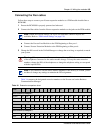
• Figure 55 shows the wiring pin-out for an BRI to the service provider.
Figure 55 BRI RJ45 wiring array
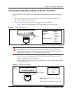
3 Insert the connector into the jack on the module.
4 You can now use the Unified Manager to configure the lines or sets associated with the
module.
Refer to the Business Communications Manager Programming Operations Guide for steps
about changing the default settings for each line/loop.
Warning: The BRI must only be connected to an NT1 provided by the service provider.
The NT1 must provide a Telecommunication Network Voltage (TNV) to Safety Extra
Low Voltage (SELV) barrier.
8 7 6 5 4 3 2 1
BRI connector
RJ45 sockets
Pin #/connection System side
1 not used
2 not used
3+RX
4 +TX
+TX
+RX
5- TX
6-RX
- RX
-TX
7 not used
8 not used