


Chapter 9 Starting the system 141
Installation and Maintenance Guide
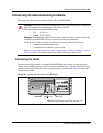
Checking system power and status
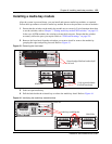
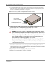
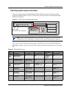
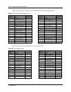
After you connect power to the BCM1000, the Power LED on the front of the base unit and
expansion unit lights. Refer to Figure 47. Once the system services have reactivated, the Status
LED turns solid green.
Figure 47 LEDs confirm that BCM1000 is active
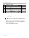
Table 26 describes the possible operating states of the LEDs on the front of the BCM1000. The
BCM1000e has both a power and a status LED, which provide the same indicators as for the base
unit.
Note: During system initialization, the system performs diagnostics on the hardware
configuration size and installation. If the power fails, system data remains in memory.
Table 26 BCM1000 LED states
LED
Label
Description Green LED On Green LED Flash
Red LED On
(Only)
Green LED Off
Indicates state of
system power.
OK N/A a minimum of 1
PS needs
attention
N/A
Indicates access to
the system disk drive
indicates heavy
activity to the disk
drive
N/A N/A N/A
Indicates condition of
system status
all monitored
services are
functioning
in startup/
shutodown mode
N/A not all services are
working
1 PCI Device/
WAN Port #1
Device is present
and the driver is
active
driver is not running N/A Device is not
present.
2 PCI Device/
WAN Port #2
Device is present
and the driver is
active
driver is not running N/A Device is not
present.
3 PCI Device Device is present
and the driver is
active
driver is not running N/A Device is not
present.
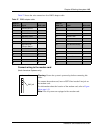
power/status
These two LEDs are solid green