


16 BCM1000 version 3.0 addendum
simply install four modules on one DS30 bus, with the dip switches set to the four offsets. The exception is for
DS30 06 and 07 if they are set to PDD. In that instance, you can still only install two ASM8s per bus.
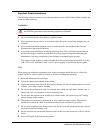
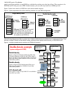
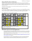
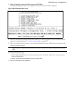
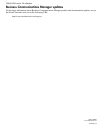
Figure 2 shows how much of a DS30 bus each station module requires.
Figure 2 Space requirements for station media bay modules, on a per-DS30 configuration
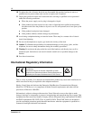
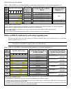
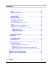
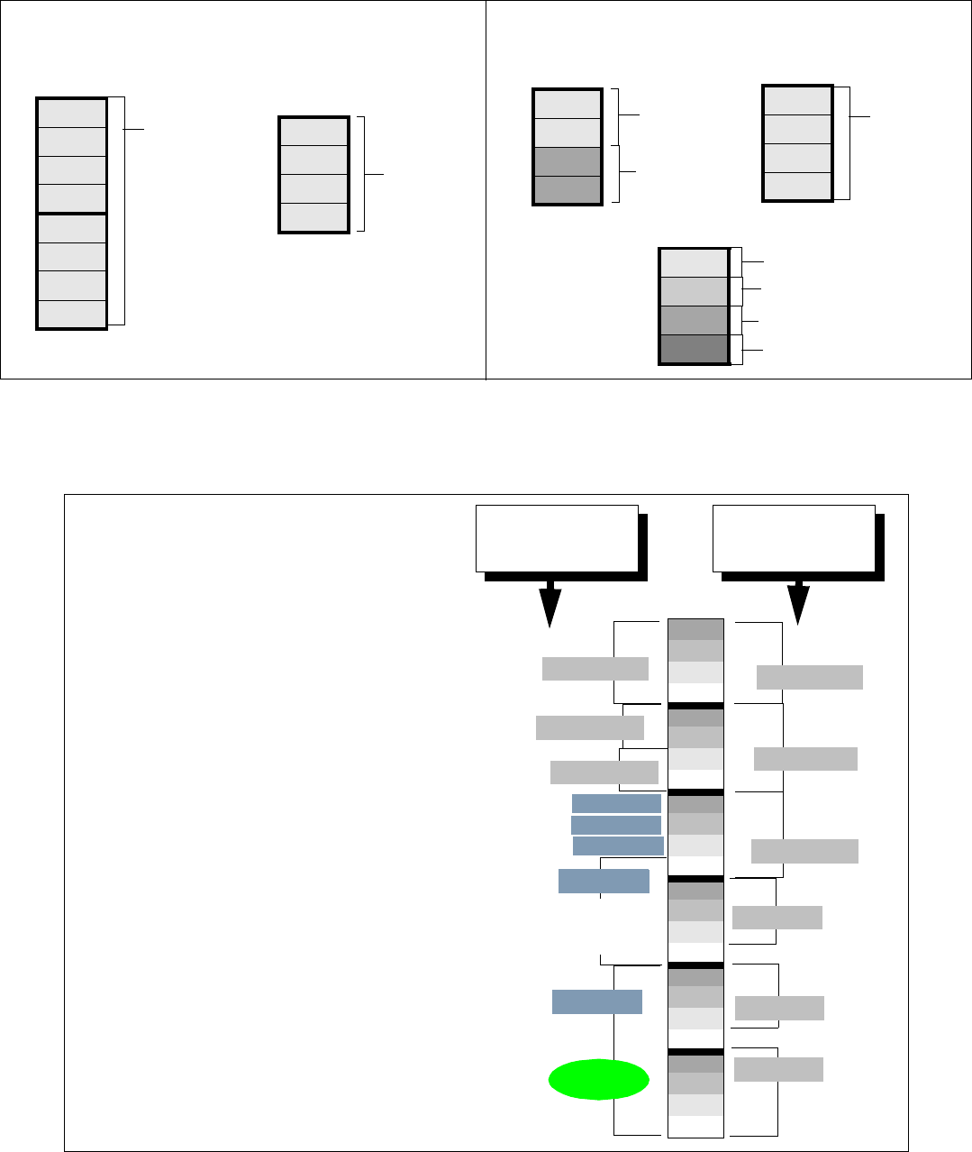
The following diagram provides a system view of what double density looks like from a system perspective. Note
that this example is based on the default setting, which provides partial double density to DS30 06 and 07.
Figure 3 Assigning double density modules to the DS30 bus hierarchy
Single-density mode
Double-density mode
4 DD ASM8s
1 DS30 bus/
per DS30
2 DD
per DS30
1 DS30 bus
1 DD
per DS30
1 DS30 bus
1 DSM 16
per DS30
1 DS30 bus/
offset set to 0
1 DSM 32
per 2 DS30s
2 DS30 buses/
offset set to 0
PDD note: If DS30 6 and 7 are in partial
double density mode, you can only
install modules set to single density. This
also means that only two ASM8s could
be installed on each DS30 bus.
DSM 16+
DSM 32+
Partial density
Systems configured with Partial double density (PDD), allow
Companion telephones on DS30 06 and 07 (if the system is
set to a 2/6 split). In this configuration, DS30 06 and 07 only
allow single-density modules. DS30 02 to 05 are set to allow
double density modules.
Double density
Systems configured with Full double density (FDD), do not
allow Companion telephones. All DS30s are set to allow
double density modules.
3/5 channel split
If your system is set to a 3/5 split, DS30 07 is not available to
any media bay modules.
02
03
04
05
06
DS30
buses
4X16
DD DSM 32+
Example of
North American-
based setup
Example of a
European- based
setup
DD DSM 32+
DS30 5 supports
the station module
part of the 4X16
BRI
SD DSM 32
Companion
BRI
DECT
DD DSM 32+
DD DSM 32+
Double-density example
07*
(system configured as PDD)
DD DSM 16+
DD DSM 16+
CTM
CTM
CTM