


Chapter 10 Wiring the modules 159
Installation and Maintenance Guide
Wiring media bay modules to internal connections
After you have the trunk modules wired, you can install the wiring to the station modules. These
are the modules which connect to the internal telephone sets.
All station module wiring uses 25-pair cable with a female amphenol connector at the media bay
module end.
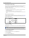
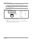
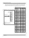
Follow these steps to connect the wiring for the DSM 16, DSM 32, ASM 8, or 4X16 modules:
1 Wire 16 wire pairs from the amphenol connector to the local connecting blocks so they
connect to the 16 station sets you want connected to this module.
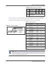
Use Table 32 and Figure 56 on page 160.
For an overview of BIX wiring conventions, refer to the Business Communications Manager
2.5 BIX Box Wiring Guide.
2 Install the telephones and peripheral equipment wiring (if new system):
a Attach the cables for the telephones to the connecting blocks.
b Install the telephones. Each telephone comes with hardware installation instructions.
Refer also to Chapter 14, “Installing optional telephony equipment,” on page 207.
c To connect analog equipment to a digit line, refer to Chapter 13, “Installing Analog
Terminal Adapters,” on page 197.
Note: DSM 32 modules require two 25-pair cables.
Note: Use 16 wire pairs from each connector for the DSM 32.
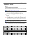
Note: If you are connecting an DSM 16, 4X16, or DSM 32, use Table 32 on page 160.
If you are connecting an ASM 8, use the Table 33 on page 161.
Note: You can configure most types of telephones before they are installed. Refer to the
Programming Operations Guide for specific instructions about telephone settings and
using the New Users Wizard to set up telephones.