Attendant consoles Page 75 of 504
Telephones and Consoles Description, Installation, and Operation
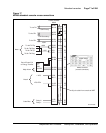
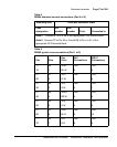
Note 1: Connect to Pin 3 or 28 of the appropriate PFJ5 terminal block.
Note 2: Connect TC to Pin 29 or 5 and ALM to Pin 4 or 31 of the
appropriate PFJ5 terminal block.
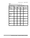
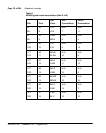
Table 9
M2250 typical cross-connections (Part 1 of 2)
Pair Pins
Pair
Color
DLC
Connections
ISDLC
Connections
1T
1R
26
1
W-BL
BL-W
Unit
0
Unit
0
2T
2R
27
2
W-O
O-W
Unit
1
Unit
8
3T
3R
28
3
W-G
G-W
Unit
2
Unit
1
4T
4R
29
4
W-BR
BR-W
Unit
3
Unit
9
5T
5R
30
5
W-S
S-W
Unit
4
Unit
2
6T
6R
31
6
R-BL
BL-R
Unit
5
Unit
10
7T
7R
32
7
R-O
O-R
Unit
6
Unit
3
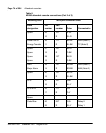
Table 8
M2250 attendant console connections (Part 3 of 3)
Mounting cord 16/25-pair connector cable
Lead
designation
Pin
number
Pair
number
Color Connected to


