Page 392 of 504 Appendix C: Meridian Modular Telephones add-on modules installation
553-3001-367 Standard 3.00 August 2005
16 Tighten the screws
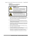
• Reconnect all cords, connect the new 24v AC transformer to the set.
• Plug in the new transformer into the 110v AC commercial electrical
outlet.
• Place the telephone in the normal operating position.
Note 1: Place the label supplied with the MPDA or MCA on the outside
of the bottom cover of the telephone. This allows proper identification and
tracking of the option level of the set.
Note 2: If an ADM3, ADM5, or ADM11 terminal is used in conjunction
with the DB-25 connector-C interface connector in the Asynchronous
Programmable Data Adapter, pin 22 in the DB-25 connector cable must
be disconnected. These ADM terminals will go into test mode if this pin is
not disconnected.
End of Procedure
Procedure 69
Connecting the data terminal
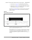
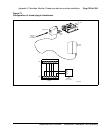
1 Connect the DB-25 connector-C interface connector from the data
terminal to the matching header connector in the back of the telephone.
2 Insert the two captive screws in the connector body into the threaded
holes in the header connector and secure tightly to prevent accidental
disconnection during data terminal operation.
End of Procedure
Power Supply Board (NTZK models)
Use the following procedures to add a Power Supply Board to the telephone
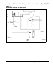
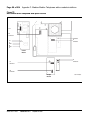
for connection to a transformer or closet power supply. Use Procedure 70 on
page 393 for the M2006 and M2008. Use Procedure 71 on page 397 for the
M2616 and M2216ACD.


