


Appendix C: Meridian Modular Telephones add-on modules installation Page 387 of 504
Telephones and Consoles Description, Installation, and Operation
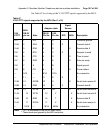
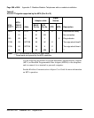
See Table 67 for a listing of the V.35 CCITT signals supported by the MCA.
Table 67
V.35 CCITT signals supported by the MCA (Part 1 of 2)
V.3 5
CCITT
MCA
DB-25
pin no.
Abbr.
Adaptor cable
Signal
Source
Description
DB-25
Pin No.
V.35
Pin No.
DTE MCA
101 1 DG 1 A Protective ground*
103A 2 SDA 2 P X Transmit data A
104A 3 RDA 3 R X Receive data A
105 4 RTS 4 C X Request to send
106 5 CTS 5 D X Clear to send
107 6 DSR 6 E X Data set ready
102 7 S 7 B Signal ground
109 8 CD 8 F X Carrier detect
— 9/10 — 9/10 CC/L No connection
— 11 — 11 K X **
115B 12 SCRB 12 X X Serial clock receive B
103B 13 SDB 13 S X Transmit data B
114B 14 SCTB 14 AA X Serial clock transmit B
114A 15 SCTA 15 Y X Serial clock transmit A
104B 16 RDB 16 T X Receive data B
115A 17 SCRA 17 V X Serial clock receive A
— 18/19 — 18/19 M/HH No connection
Note: * Pin 1 is connected to the MCDS shelf frame.
** These leads are ignored by the MCA controller.