


Page 72 of 504 Attendant consoles
553-3001-367 Standard 3.00 August 2005
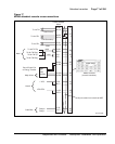
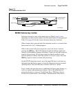
The following notes refer to Figure 17 on page 71, which illustrates the
M2250 attendant console cross-connections.
Note 1: The M2250 is powered by means of the line circuits. In addition
to the primary TN, secondary TN, and ASM TN, two TNs are cabled to
the M2250 using the +AUX and –AUX leads. The maximum loop length
is 3000 ft of 24 AWG wire.
Note 2: When additional options are used (BLF or display backlight
option), an additional 16 V DC power supply is required. The 16 V DC
source is cabled using +VPS and VPS RTN leads. The maximum
distance from the console to the power source is 120 feet of 24 AWG
wire. Please note: if both options are installed, only one 16 V DC power
supply is required.
Note 3: Nortel recommends that five consecutive TNs on the line circuit
be allocated for each console.
Note 4: When used with the ISDLC, the M2250 requires NT8D02 or
later.
Note 5: The third TN must be cross-connected to the console cable
WH/SL pair whether or not an ASM (Attendant Supervisory Module) is
installed. This third TN provides additional console power which is
required.
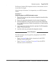
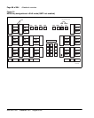
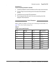
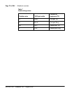
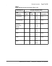
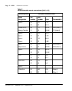
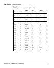
Table 8 on page 73 explains where each M2250 cable pair is connected.
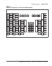
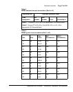
Table 9 on page 75 lists the M2250 typical cross-connections.