


Page 422 of 504 Appendix C: Meridian Modular Telephones add-on modules installation
553-3001-367 Standard 3.00 August 2005
13 Insert the three (four if there are two modules) self-tapping, Phillips-head
screws supplied with the Key Expansion Module into the mounting holes
in the bottom of the footstand. Tighten firmly with a #1 Phillips
screwdriver.
Note: Place the label supplied with the Key Expansion Module(s) on the
outside of the bottom cover or footstand of the telephone. This allows
proper identification and tracking of the option level of the set.
14 Perform the self-test (see Procedure 62 on page 358) and acceptance
test procedures. See LD 31 in the Software Input/Output: Administration
(553-3001-311).
End of Procedure
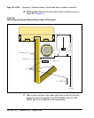
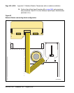
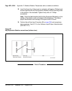
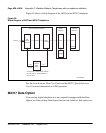
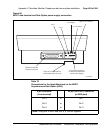
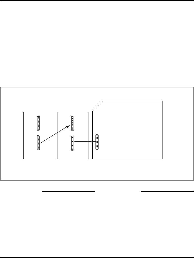
Figure 82
Key Expansion Module connections (bottom view)
First Key
Expansion Module
Second Key
Expansion Module
Set
553-AAA0648