


Page 398 of 504 Appendix C: Meridian Modular Telephones add-on modules installation
553-3001-367 Standard 3.00 August 2005
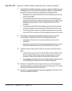
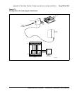
10 Take the self-tapping Phillips-head screws supplied with the power supply
board and install them into the mounting holes. Tighten firmly with a #1
Phillips screwdriver.
11 If the telephone has a display, reconnect the display ribbon cable, routing
the cable as described in Procedure 73 on page 405.
Note: Do not allow R5 on the power supply board to become bent during
this procedure.
12 Replace the base. If the telephone is equipped with an MPDA or MCA,
reconnect the data cable to the base telephone jack and replace the
footstand (ensuring the MPDA or MCA cable does not get pinched
between the base and footstand). Make sure the footstand is firmly seated
to the base.
Note: Place the label supplied with the power supply board on the
outside of the bottom cover of the telephone. This allows proper
identification and tracking of the option level of the set.
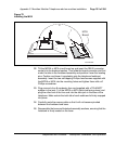
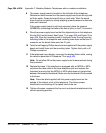
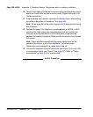
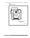
13 Connect the telephone to a local transformer (see Figure 73 on page 399)
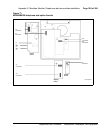
or closet power supply (see Figure 74 on page 400). Refer to “Power
requirements” on page 345 for requirements.
End of Procedure