


Page 394 of 504 Appendix C: Meridian Modular Telephones add-on modules installation
553-3001-367 Standard 3.00 August 2005
8 The power supply board is located on the left side of the telephone.
Remove two small screws from the power supply board (near the top) and
set them aside. Grasp the board firmly on each side. Work the board
loose from the connector by slowly applying upward pressure to alternate
sides until released.
If the power supply board is not being replaced, place the jumpers
(A0288529) connecting the bottom two sets of pins on the P1 connector.
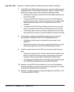
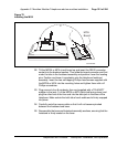
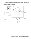
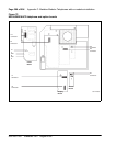
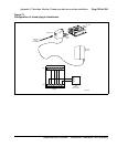
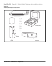
9 Place the power supply board so that the alignment pin on the telephone
fits into Slot A on the board. See Figure 71 on page 395 and Figure 72 on
page 396. Align the mounting holes in the board (near the top) over the
mounting holes in the telephone and carefully press down so that the H1
connector on the board slides onto the P1 pins.
10 Take the self-tapping Phillips-head screws supplied with the power supply
board and install them into the mounting holes. Tighten firmly with a #1
Phillips screwdriver.
11 If the telephone has a display, reconnect the display ribbon cable, routing
the cable as described in Procedure 73 on page 405.
Note: Do not allow R5 on the power supply board to become bent during
this procedure.
12 Replace the base. If the telephone is equipped with an MPDA or MCA,
reconnect the data cable to the base telephone jack and replace the
footstand (ensuring that the MPDA or MCA cable does not get pinched
between the base and footstand). Make sure the footstand is firmly seated
to the base.
Note: Place the label supplied with the power supply board on the
outside of the bottom cover of the telephone. This allows proper
identification and tracking of the option level of the set.
13 Tighten all screws, reconnect the line cord, and place the telephone in the
normal operating position.