


Page 402 of 504 Appendix C: Meridian Modular Telephones add-on modules installation
553-3001-367 Standard 3.00 August 2005
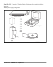
8 Remove the base from the telephone.
Attaching the Power Module
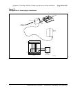
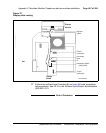
9 Lay the Power Module assembly into position on the left side of the
telephone. Be careful not to bend R5 (the big disk) on the Power Module
during installation.
10 If you are adding a Power Module to the set for the first time (not replacing
an existing Power Module), the connector (J2 on the M2006 and M2008/
M2008HF, P1 on the M2616) on the main board should have jumpers
which must be removed at this point.
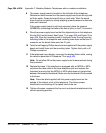
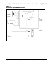
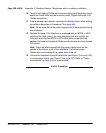
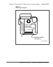
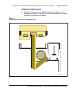
11 Connect the Power Module to the main board with the ribbon cable,
keeping the red edge of the ribbon cable from the front of the telephone
as show in Figure 75.
12 Screw the Power Module into position on the left side of the telephone.
CAUTION
Damage to Equipment
This is a polarity-sensitive connection. The cable and
the connector on the main board (J2 on the M2006
and M2008/M2008HF, and P1 on the M2616) are
keyed.