


Page 290 of 504 Digital telephones line engineering
553-3001-367 Standard 3.00 August 2005
Engineering a telephone line
Use Procedure 45 on page 290 to engineer a digital telephone line.
Procedure 45
Engineering a telephone line
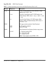
1 Be sure that cable pair selections meet the following requirements:
• AC signal loss is less than 12 dB at 256 kHz due to all sources.
• DC loop resistance is less than 175 ohm.
• Minimum loop length (mainframe bulkhead to telephone) is
30 m (100 ft).
• Near-end crosstalk coupling loss is >38 dB at Nyquist frequency of
256 kHz (not an issue for typical 22, 24, and 26 AWG twisted pair
cable).
• No bridge taps are permitted.
• No loading coils are permitted.
• Protection devices of the carbon-block and gas-filled type are
permitted if the off-state shunting impedance is better than 10 M¾
resistive and less than 0.5 pF capacitive.
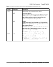
2 Be sure that the following criteria are met where under-carpet cabling is
used:
• Characteristic impedance is at 256 kHz, 100 ± 10 ohm.
• Insertion loss is at 256 kHz, <4.6 dB/kft.
• The next pair-to-pair coupling loss is at 256 kHz, >40 dB.
3 For a typical system with 22, 24, or 26 AWG standard twisted-pair cable,
the requirements translate to the following allowable loops:
• up to 915 m (3000 ft) of 22 or 24 AWG cable
• up to 640 m (2100 ft) of 26 AWG cable
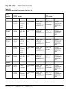
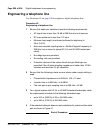
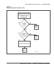
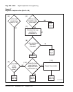
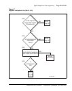
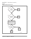
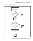
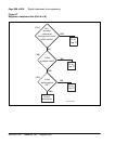
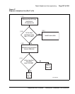
4 If the selected cable pair does not work satisfactorily, select another cable
pair as shown in Figure 47.
End of Procedure