


M3900 installation and configuration Page 189 of 504
Telephones and Consoles Description, Installation, and Operation
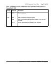
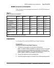
M3900 set power consumption
Table 35 shows power consumption measurements of the M3900 telephones
in various states.
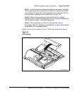
Installation
Use Procedure 28 to install the M3900 Series Digital Telephone
Procedure 28
Installing the M3900 Series Digital Telephone
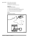
1 Complete the wiring and cross-connections (loop power).
Note: The M3901, M3902, and M3903 are polarity sensitive. The Tip and
Ring connections from the telephones to the Digital Line Cards (DLC)
must be connected directly. If the Tip and Ring signals are crossed on an
M3901, M3902, or M3903, the telephone will not function.
2 Connect the telephone to the connecting block.
3 Place the telephone upright on the desk in the normal operating position.
Table 35
M3900 set power consumption
M3901 M3902 M3903 M3904 M3905
Idle 29.3 37.3 42.5 31.5 15.02
H/F Nominal N/A 45.7 48.7 37.5 N/A
H/F Maximum N/A 64.3 59.7 46.4 N/A
DBA Idle N/A N/A N/A 39.29 15.31
DBA H/F Nominal N/A N/A N/A 45.9 N/A
DBA H/F N/A N/A N/A 52 N/A
Maximum 2 KBA
Idle
N/A N/A N/A 33.42 14.98
Note: All measurements are in milli-amps.