


Attendant consoles Page 39 of 504
Telephones and Consoles Description, Installation, and Operation
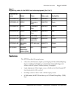
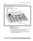
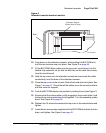
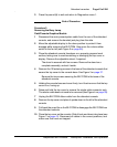
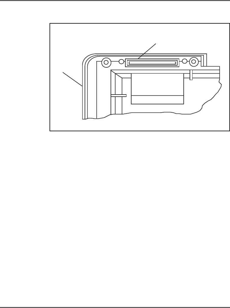
Figure 5
Attendant console knockout section
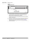
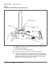
10 Push down on the attendant console, while holding the BLF/CGM unit,
until the two locators snap into place. See Figure 6 on page 40.
11 Fit the BLF/CGM ribbon cable onto the top cover circuit board, into the
flexible strip connector J4 (so that the blue line on the cable faces away
from the circuit board).
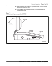
12 Hold the top cover over the attendant console and reconnect the cable
connector(s) onto the base of the attendant console.
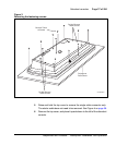
13 Place the top cover on the console. Slide it back and down into place. See
Figure 7 on page 41. Check that all the cables are in the correct positions
and that none are trapped.
14 Push the BLF/CGM display into position by rotating it back (see Figure 7).
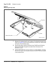
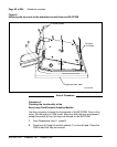
15 Ensuring that the volume slider is fully engaged in the correct slider, hold
the top cover and console base firmly together. Turn the assembly upside
down. See Figure 8 on page 42.
16 Reinsert the 12 screws that secure the top cover to the console base and
tighten.
17 Insert the two new screws supplied with the BLF/CGM that attach it to the
base, and tighten. See Figure 8 on page 42.
Base
Knockout Section
(Clean Away 6 Tags)
553-AAA0629