


Digital telephones line engineering Page 301 of 504
Telephones and Consoles Description, Installation, and Operation
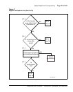
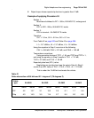
Procedure 48
Testing insulation resistance
1 Set the VOM range switch to ohm x 10,000 and adjust the meter to zero.
2 Connect the VOM test probes to the loop at the line card or distribution
frame.
3 Measure the resistance between the following points under no-load
conditions:
• T and R
• T and GND
• R and GND
Requirement: Resistance readings must be greater than 10 M ohm.
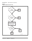
Procedure 49
Testing DC continuity
1 Short circuit the T and R at the far end.
2 Using the VOM, measure the resistance between the T and R.
Requirement: Resistance measurement should be approximately
equal to the calculated loop resistance as described in Procedure 46
on page 299.
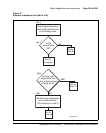
Procedure 50
Testing capacitance unbalance
1 Using the cable analyzer, measure the capacitance between the following
points:
• T and GND
• R and GND
Requirement: The difference between the two readings must be
<0.002 µF>.