


Page 380 of 504 Appendix C: Meridian Modular Telephones add-on modules installation
553-3001-367 Standard 3.00 August 2005
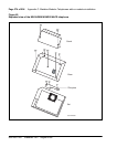
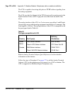
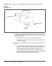
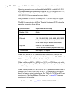
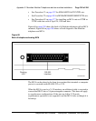
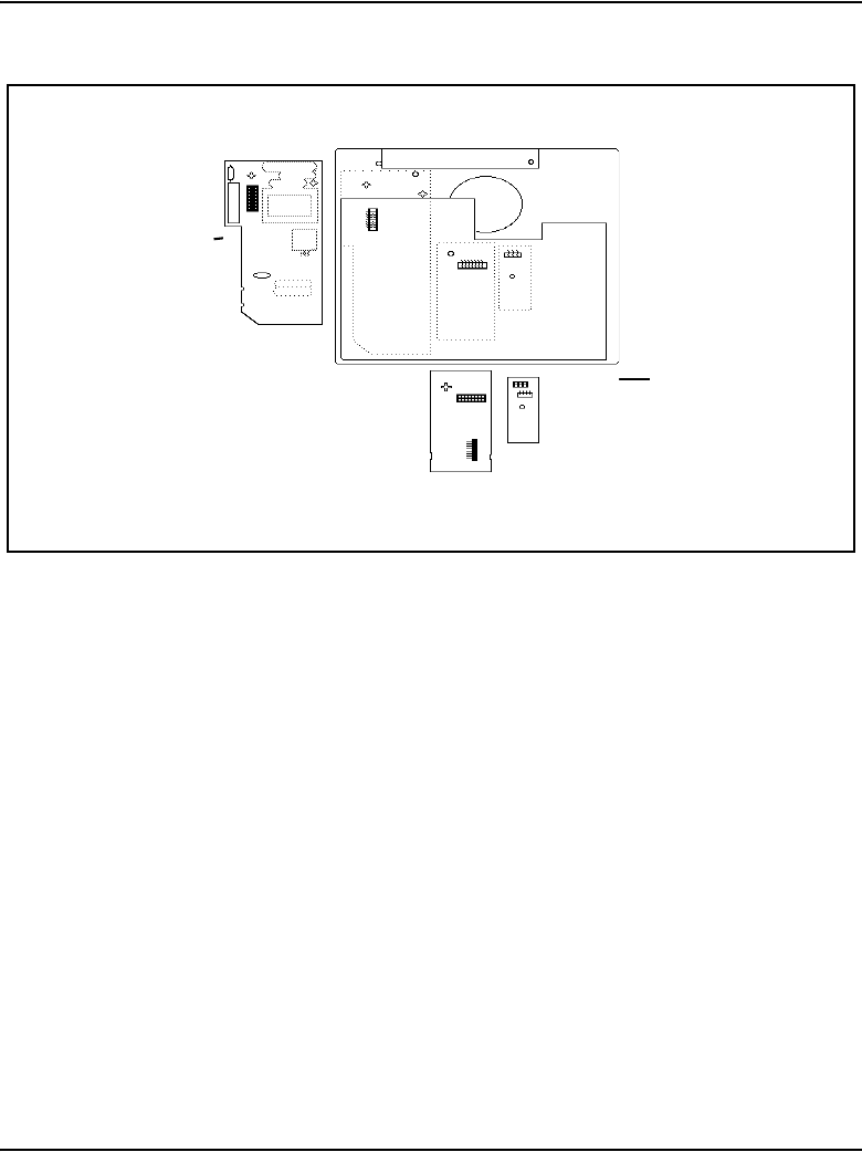
Figure 67
Connector view
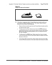
11 If the phone is equipped with the External Alerter Option, remove it before
installing the ATA. The External Alerter Option board is located at the right
center of the telephone:
• Remove the screws from the External Alerter Option board.
• Grasp the board firmly on each end and pull upward to remove from
the 2X3 pin connector
12 Install the Jumper board on the 2X7 pin connector inside the phone set
base.
• There are 2 Jumper boards provided. Use the brown Jumper board
for the NTZKxxxx phone set and the black Jumper board for the
NT2Kxxxx phone set with a date code prior to April 24, 1998.
• If a Power Option board was not installed on the NT2Kxxxx and the
NTZKxxxx there will be 2 Jumper plugs on the 2X7 pin connector that
must be removed before installing the Jumper board.
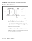
Display board
Power board
Alerter board
2x3 pin connector
2x7 pin connector
Inside Phone Base