


Appendix C: Meridian Modular Telephones add-on modules installation Page 381 of 504
Telephones and Consoles Description, Installation, and Operation
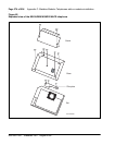
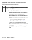
13 Remove the knockout located on the back panel of the footstand in order
to install the ATA. It is the smaller knockout, located inside the large
knockout. The small ATA knockout can be remove by pressing it in with
thumb presser.
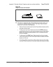
14 Install the ATA Printed Circuit board into the footstand.
15 Plug the ATA 8-conductor line cord, included in the package, into the data
jack in the base of the telephone. Plug the other end of this cord into the
data jack of the ATA located in the footstand.
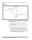
16 Reassemble the footstand on the base and screw it into position using a
#1 Phillips screwdriver.
17 Plug the 24v AC Power Transformer into the circular mini DIN connector
on the backpanel of the footstand.
18 Plug the transformer end of the AC Power Transformer into the AC
commercial electrical outlet.
19 The analog device can now be connected to the RJ11 connector on the
back of the footstand. Refer to the manufacturer’s documentation for
installation instructions for the FAX, modem, or telephone to be used.
End of Procedure
Meridian Communications Adapter and Meridian
Programmable Data Adapter
The Meridian Communications Adapter (MCA) replaces the Meridian
Programmable Data Adapter (MPDA), and offers enhanced capability over
the MPDA.
Functional description
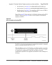
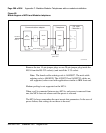
The MCA mounts within the telephone. It enables synchronous and
asynchronous ASCII terminals and personal computers to be connected to the
telephone using an RS-232-C or V.35 interface on a DB-25 connector. See
Figure 68 on page 385.
The MCA enables synchronous applications (DTEs such as video
conferencing equipment and Group IV fax units) to be connected to the