


Appendix C: Meridian Modular Telephones add-on modules installation Page 391 of 504
Telephones and Consoles Description, Installation, and Operation
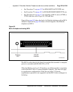
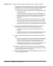
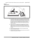
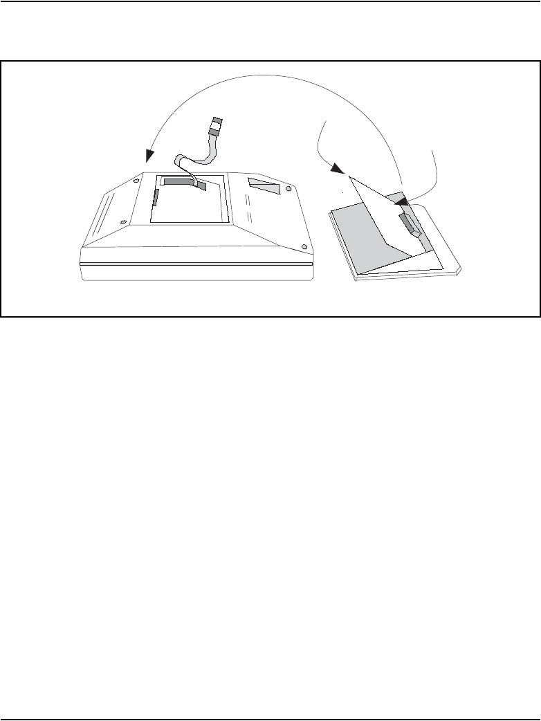
12 Tilt the MPDA or MCA circuit board up and insert the DB-25 connector
socket into the breakout section. Then slide the board connector end-first
under the tabs in the footstand assembly and position it over the locating
pins. Position and lower it completely onto the telephone footstand
assembly. Insert the two self-tapping Phillips-head screws supplied with
the MPDA or MCA into the mounting holes and tighten them with a #1
Phillips screwdriver.
13 Plug one end of an 8-conductor line cord supplied with a TELADAPT
adapter in the jack J1 of the MPDA or MCA (latch tab facing down) and
plug the other end of the line cord into the data jack in the base of the
telephone. Make certain the latch tab of each cable end is firmly snapped
into place.
14 Carefully route the excess cable so that it will not become pinched
between the footstand and base.
15 Reassemble the base and footstand assembly sections, ensuring that the
footstand is firmly seated on the base.
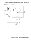
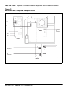
Figure 70
Installing the MCA
2
1
MCA
Board
553-AAA0637