Attendant consoles Page 35 of 504
Telephones and Consoles Description, Installation, and Operation
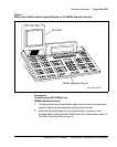
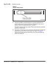
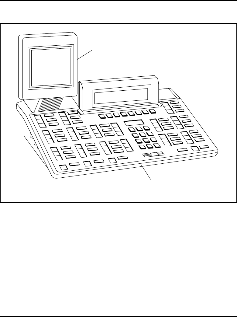
Figure 1
Busy Lamp Field/Console Graphics Module on the M2250 attendant console
Procedure 1
Connecting the BLF/CGM to the
M2250 attendant console
1 Disconnect the main power/system cable from the rear of the attendant
console, and remove the handset jack plug from the side.
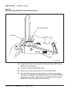
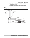
2 Move the adjustable display to the down position to protect it from
damage while installing the BLF/CGM. Move the volume slider switch to
the far left. See Figure 2 on page 36.
BLF/CGM
M2250 Attendant Console
553-AAA1718.EPS


