


Attendant consoles Page 49 of 504
Telephones and Consoles Description, Installation, and Operation
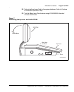
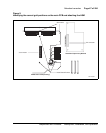
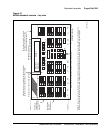
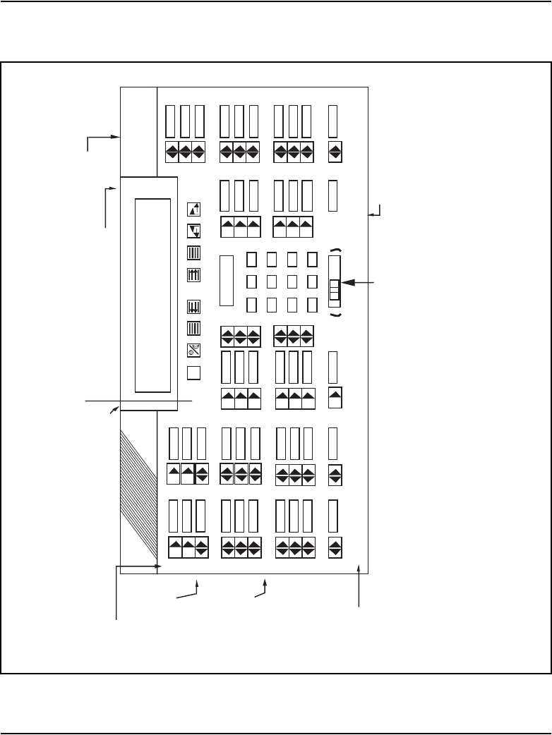
Figure 10
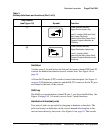
M2250 attendant console – top view
Display screen (can be tilted upwards)
Rows
9
7
6
8
5
4
3
2
1
0
*
1
4
7
2
5
8
0
3
6
9
#
AK
BK
CK
AI
BI
CI
DI/EI
EI
EK
FI
FK
Hold
Shift
Conf
RL.Des
RL.Src
EX.Des
EX.Scr
RS-232 Connector for
connection to PC with Monitor
Slider Control for Handset or Headset Volume Adjustments
Backlighting
ON/OFF
Slider Switch
(1)
(2)
(3)
(4)
(5)
(6)
(7)
(8)
Arbitrary Icon key numbering for test identification
purposes only (not designated on the console)
Columns
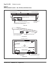
Power Fail Transfer Switch
(in base of console)
Handset or
headset jacks
(in both sidesof
console)
25-pin subminiature D-type male
connector for cable connecting
console to distributing frame
Note:
Rows and columns are labeled with numbers and letters respectively in order to allow textual references when identifying t
he
location of specific components. In the column designations, the letter I stands for indicators, and the letter K signif
ies keystrips.
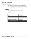
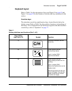
Directory Number
Display line 1
Display line 2
Display line 3
Display line 4
C/H
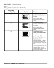
C
D0
D1
D2
F
A
B
Display 1
Display 2
or
553-AAA0566