


Page 34 of 504 Attendant consoles
553-3001-367 Standard 3.00 August 2005
Installation
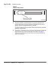
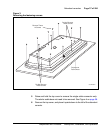
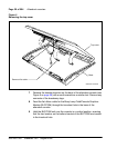
The BLF/CGM mounts on the back of the attendant console and is held on by
snap-fits and screws. It is connected to the console using a 16-way connector
that is located on the keyboard Printed Circuit Board (PCB). This connector
is accessed through a rectangular knockout section located underneath the
casing overhang at the Meridian logo location. The attendant console’s top
cover must be removed to install the BLF/CGM.
Refer to the following procedures to install the BLF/CGM:
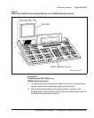
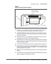
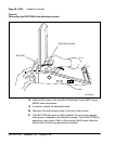
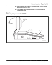
• Procedure 1, “Connecting the BLF/CGM to the M2250 attendant
console”, on page 35
• Procedure 2, “Checking the functionality of the Busy Lamp Field/
Console Graphics Module”, on page 42
• Procedure 3, “Removing the Busy Lamp Field/Console Graphics
Module”, on page 43
Refer to the M1250/M2250 Attendant Console User Guide or the Busy Lamp
Field/Console Graphics Module User Guide for further information.
CAUTION WITH ESDS DEVICES
Follow normal antistatic precautions when installing the
BLF/CGM on the attendant console.