


Analog (500/2500-type) telephones Page 313 of 504
Telephones and Consoles Description, Installation, and Operation
Cross-connect the telephones
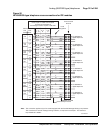
Be sure to connect the telephones as shown in Figure 50 on page 315.
Figure 50 on page 315 provides the diagram for cross-connecting analog
(500/2500-type) telephones on an Intelligent Peripheral Equipment (IPE)
module.
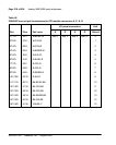
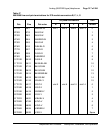
Table 46 on page 316, Table 47 on page 317, and Table 48 on page 318 show
analog (500/2500-type) telephone cross-connections on an Intelligent
Peripheral Equipment (IPE) module.
Follow the steps in Procedure 60 to cross-connect analog (500/2500-type)
telephones.
Procedure 60
Cross-connecting the telephones
1 Locate the telephone terminations at the cross-connect terminal.
Telephone terminations are located on the vertical side of the frame when
frame-mounted blocks are used and in the blue field when wall-mounted
blocks are used.
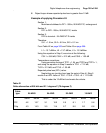
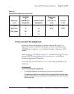
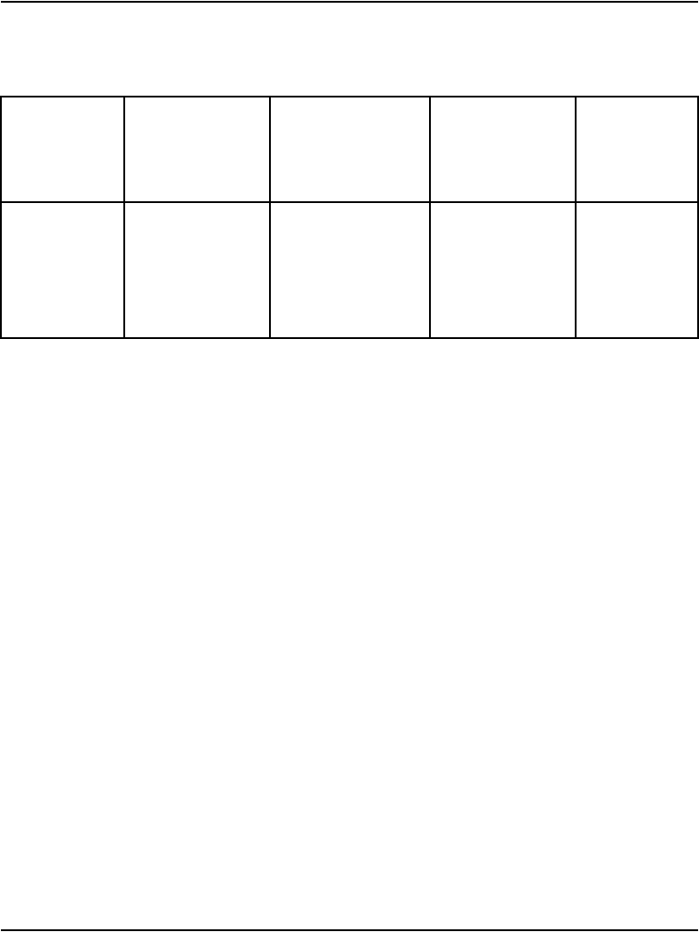
Table 45
NE-500/2500 telephone connections
Mounting
cord
NE-47QA
or
QBBIB block
designation
NE-284-74-5001
designation
Cable color
pairs
(16 to 25 not
used)
Connect
to TN
TIP (green) G 1T W-BL TIP
RING (red) R 1R BL-W RING
GND (yellow) BK X2
Y X1