


Appendix C: Meridian Modular Telephones add-on modules installation Page 417 of 504
Telephones and Consoles Description, Installation, and Operation
Removing the External Alerter Board
7 The External Alerter Board is located at the right center of the telephone.
Remove the screws from the board. Grasp the board firmly on each end
and pull upward to remove.
Installing the External Alerter Board
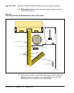
8 Place the H1 connector of the External Alerter Board over the P3 pins of
the telephone (see Figure 71 on page 395 for M2006/M2008; see
Figure 72 on page 396 for M2616/M2216ACD). Align the mounting hole
over the mounting post. Carefully work H1 onto the P3 pins until firmly
seated. Place the self-tapping Phillips-head screw supplied with the
External Alerter Board into the mounting hole and tighten it with a #1
Phillips screwdriver.
9 To signal the External Alerter when the telephone’s handset or speaker is
active, place the jumpers (AO288529) connecting the two right-most pins
on the alerter board.
To signal the External Alerter when the telephone is ringing or buzzing,
place the jumpers connecting the two left-most pins on the External
Alerter Board.
10 If the telephone is not yet equipped with the power supply board, install it
(see Procedure 70 on page 393 for M2006/M2008; see Procedure 71 on
page 397 for M2616/M2016S/M2216ACD).
Note: Do not allow R5 on the power supply board to become bent during
this procedure.
11 Replace the base. If the telephone is equipped with an MPDA or MCA,
reconnect the data cable to the base telephone jack and replace the
footstand (ensuring that the MPDA or MCA cable does not get pinched
between the base and the footstand). Make sure the footstand is firmly
seated in the base.
12 Tighten all screws, reconnect the line cord, and place the telephone in the
normal operating position.
Note: Place the label supplied with the External Alerter on the outside of
the bottom cover of the telephone. This allows proper identification and
tracking of the option level of the set.
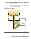
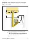
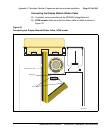
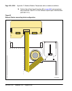
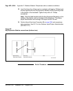
13 For the connecting block configuration, see Figure 81.