Appendix C: Meridian Modular Telephones add-on modules installation Page 385 of 504
Telephones and Consoles Description, Installation, and Operation
• See Procedure 71 on page 397 for M2616/M2216ACD NTZK sets.
• See Procedure 72 on page 401 for M2006/M2008/M2008HF NT2K sets.
• See Procedure 67 on page 377 for installing an MCA onto an NT9K or
NT2K with date code of April 24, 1998 and later.
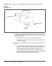
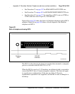
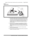
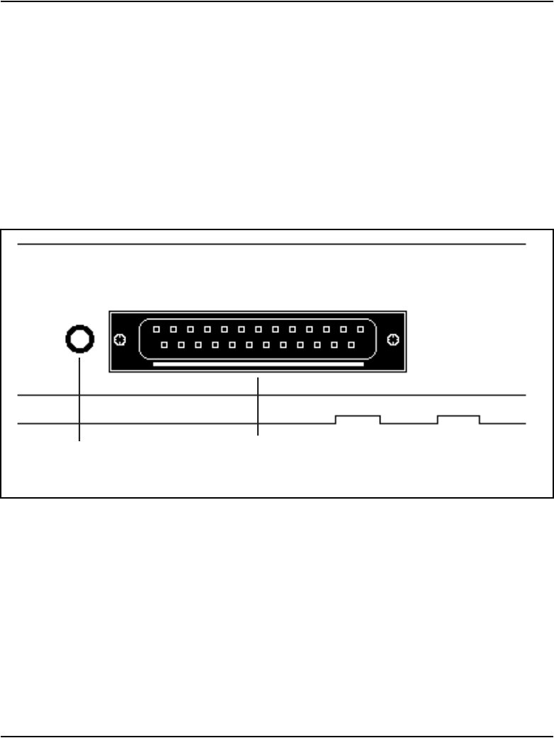
Figure 68 on page 385 shows the back of a Modular telephone with an MCA
mounted; Figure 69 on page 386 shows a block diagram of the Modular
telephone and MCA.
The MCA can be placed as far from its associated data terminal or computer
port as is consistent with EIA RS-232 or V.35.
When the MCA is used as a V.35 interface, an additional cable is required to
convert the DB-25 into a 34-pin rectangular connector. This does not apply
to asynchronous configurations. If the pins are left in V.35 mode,
asynchronous operation is not supported, and the MCA looks as though it is
locked up.
Figure 68
Back of telephone showing MCA
Flashing
LED
RS-232
interface
553-AAA0739


