


Digital telephones line engineering Page 305 of 504
Telephones and Consoles Description, Installation, and Operation
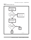
6 Reject loops whose expected pulse loss is greater than 12 dB.
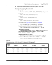
Example of applying Procedure 53
Section 1:
Mainframe bulkhead to DF1 - 500m, 26 AWG PIC, underground
Section 2:
DF1 to DF2 - 200m, 26 AWG PIC, inside
Section 3:
DF2 to terminal - 24 AWG NT D-inside
Therefore:
SL1 = 1.5 km, SL2 = 0.2 km, SL3 = 0.1 km
From Table 42 on page 305 and Table 43 on page 306:
L1 = 13.7 dB/km, L2 = 13.7 dB/km, L3 = 13.3 dB/km.
Using the equation in Step 2, we arrive at the following:
CSL1 = 6.85 dB, CSL2 = 2.74 dB, and CSL3 = 1.33 dB
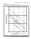
Temperature corrections:
Using correction factors of TCF1 = 1.04, and TCF2 and TCF3 = 1,
and using the equation in Step 3 results in TCL1 = 7.12 dB,
TLC2 = 2.74 dB, and TCL3 = 1.33 dB.
Expected pulse loss (EPL) value:
Neglecting any junction loss (see the note in Step 4), Step 5
results in an EPL value of TSL1 + TSL2 + TSL3 + 0 = 11.19 dB.
This is under the 12 dB limit and meets the criteria.
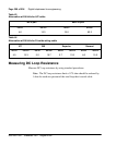
Table 42
Cable attenuation at 256 kHz and 21.1 degrees C (70 degrees F)
Cable
type
26 AWG 24 AWG 22 AWG 19 AWG
dB/kft dB/km dB/kft dB/km dB/kft dB/km dB/kft dB/km
PIC 4.2 13.7 3.1 10.2 2.5 8.1 1.7 5.6
Pulp 4.3 14.3 3.5 11.4 2.7 9.0 2.0 6.6