


Configuring IP Addressing
IP Addressing Examples
IPC-53
Cisco IOS IP Configuration Guide
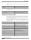
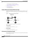
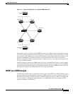
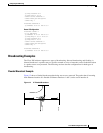
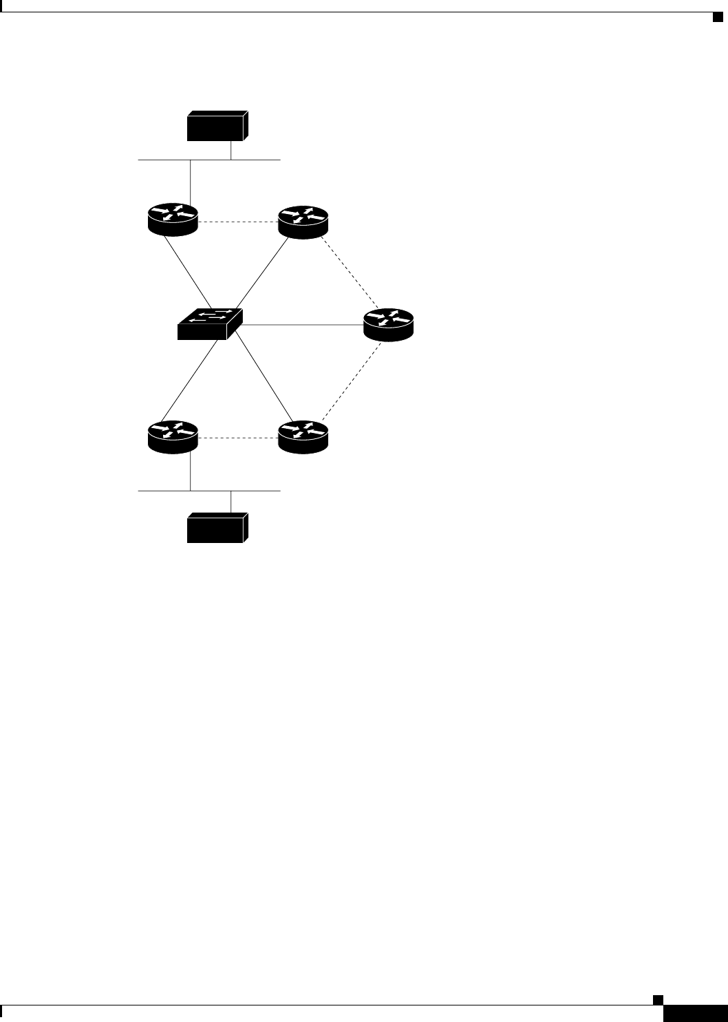
Figure 10 Physical Configuration of a Sample NBMA Network
Refer again to Figure 9. Initially, before NHRP has resolved any NBMA addresses, IP packets from the
source host to the destination host travel through all five routers connected to the switch before reaching
the destination. When Router A first forwards the IP packet toward the destination host, Router A also
generates an NHRP request for the IP address of the destination host. The request is forwarded to
Router C, whereupon a reply is generated. Router C replies because it is the egress router between the
two logical NBMA networks.
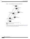
Similarly, Router C generates an NHRP request of its own, to which Router E replies. In this example,
subsequent IP traffic between the source and the destination still requires two hops to traverse the NBMA
network, because the IP traffic must be forwarded between the two logical NBMA networks. Only one
hop would be required if the NBMA network were not logically divided.
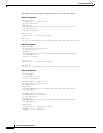
NHRP over ATM Example
The following example shows a configuration of three routers using NHRP over ATM. Subinterfaces and
dynamic routing also are used. Router A obtains an OSPF route that it can use to reach the LIS where
Router B resides. Router A can then initially reach Router B through Router C. Router A and Router B
are able to directly communicate without Router C once NHRP has resolved the respective NSAP
addresses of Router A and Router C.
Router A
Source
host
S3231
Router B
Router C
Router D
Router E
Destination
host