


Configuring Server Load Balancing
Configuration Examples
IPC-157
Cisco IOS IP Configuration Guide
standby 1 timers 5 15
standby 1 name Web-Group
interface FastEthernet 41
ip address 2.0.0.1 255.0.0.0
router eigrp 1
network 1.0.0.0
network 2.0.0.0
The standby ip interface configuration command enables HSRP and establishes 1.0.0.3 as the IP address
of the virtual router. The configurations of both Layer 3 switches include this command so that both
switches share the same virtual IP address. The number 1 establishes Hot Standby group 1. (If you do
not specify a group number, the default is group 0.) The configuration for at least one of the Layer 3
switches in the Hot Standby group must specify the IP address of the virtual router; specifying the IP
address of the virtual router is optional for other routers in the same Hot Standby group.
The standby preempt interface configuration command allows the Layer 3 switch to become the active
switch when its priority is higher than all other HSRP-configured switches in this Hot Standby group.
The configurations of both switches include this command so that each can be the standby Layer 3 switch
for the other switch. The number 1 indicates that this command applies to Hot Standby group 1. If you
do not use the standby preempt command in the configuration for a Layer 3 switch, that switch cannot
become the active Layer 3 switch.
The standby priority interface configuration command sets the HSRP priority of the Layer 3 switch to
110, which is higher than the default priority of 100. Only the configuration of Device A includes this
command, which makes Device A the default active Layer 3 switch. The number 1 indicates that this
command applies to Hot Standby group 1.
The standby authentication interface configuration command establishes an authentication string
whose value is an unencrypted eight-character string that is incorporated in each HSRP multicast
message. This command is optional. If you choose to use it, each HSRP-configured Layer 3 switch in
the group should use the same string so that each switch can authenticate the source of the HSRP
messages that it receives. The number 1 indicates that this command applies to Hot Standby group 1.
The standby timers interface configuration command sets the interval (in seconds) between hello
messages (called the hello time) to 5 seconds, and sets the interval (in seconds) that a Layer 3 switch
waits before it declares the active Layer 3 switch to be down (called the hold time) to 8 seconds. (The
defaults are 3 and 10 seconds, respectively.) To modify the default values, you must configure each Layer
3 switch to use the same hello time and hold time. The number 1 indicates that this command applies to
Hot Standby group 1.
The standby name interface configuration command associates the IOS SLB interface with an HSRP
group name (in this case, Web-Group), previously specified on an inservice (virtual server) command.
The number 1 indicates that this command applies to Hot Standby group 1.
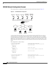
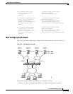
IOS SLB Stateless Backup Configuration Example
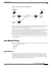
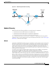
The following commands enable the HSRP standby group 100 IP address, priority, preempt, and timers;
and configures a name and authentication for Device A in Figure 26:
standby 100 ip 172.20.100.10
standby 100 priority 110
standby 100 preempt
standby 100 timers 5 15
standby 100 name Web_group1
standby 100 authentication Secret
exit