


Configuring Server Load Balancing
Configuration Examples
IPC-155
Cisco IOS IP Configuration Guide
real 10.4.1.1 port 8082
inservice
!
ip slb vservers HTTP2
! Handle HTTP (port 80) requests
virtual 128.4.0.1 tcp www
serverfarm FARM2
inservice
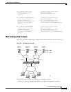
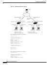
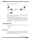
HSRP Configuration Example
Figure 26 shows the topology of an IP network with two Layer 3 switches configured for HSRP. The
following conditions exist in this network:
• Device A is the active HSRP Layer 3 switch and handles packets to the real servers with IP addresses
3.0.01 through 3.0.020.
• Device B handles packets to real servers with IP addresses 2.0.0.1 through 2.0.0.20.
• All hosts accessing the network use the IP address of the virtual router (in this case, 1.0.0.3).
• The configuration shown uses the Enhanced Interior Gateway Routing Protocol (Enhanced IGRP),
but HSRP can be used with any other routing protocol supported by the Cisco IOS software, such as
Open Shortest Path First (OSPF).
Note Some configurations that use HSRP still require a routing protocol for convergence when
a topology change occurs. The standby Layer 3 switch becomes active, but connectivity
does not occur until convergence occurs.
If the connection between Device A and the client accessing virtual IP 1.0.0.3 fails, fast-converging
routing protocols (such as Enhanced IGRP and OSPF) can respond within seconds, ensuring that
Device B is prepared to transfer packets that would have gone through Device A.