


Configuring IP Services
IP Services Configuration Examples
IPC-128
Cisco IOS IP Configuration Guide
HSRP MIB Trap Example
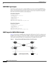
The following example shows how to configure HSRP on two routers and enable the HSRP MIB trap
feature. As in many environments, one router is preferred as the active one by configuring it at a higher
priority level and enabling preemption. In this example, the active router is referred to as the primary
router. The second router is referred to as the backup router.
Primary Router Configuration
interface Ethernet1
ip address 15.1.1.1 255.255.0.0
no ip redirects
standby priority 200
standby preempt
standby ip 15.1.1.3
snmp-server enable traps hsrp
snmp-server host yourhost.cisco.com public hsrp
Backup Router Configuration
interface Ethernet1
ip address 15.1.1.2 255.255.0.0
no ip redirects
standby priority 101
standby ip 15.1.1.3
snmp-server enable traps hsrp
snmp-server host myhost.cisco.com public hsrp
HSRP Support for MPLS VPNs Example
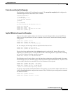
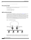
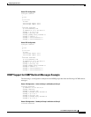
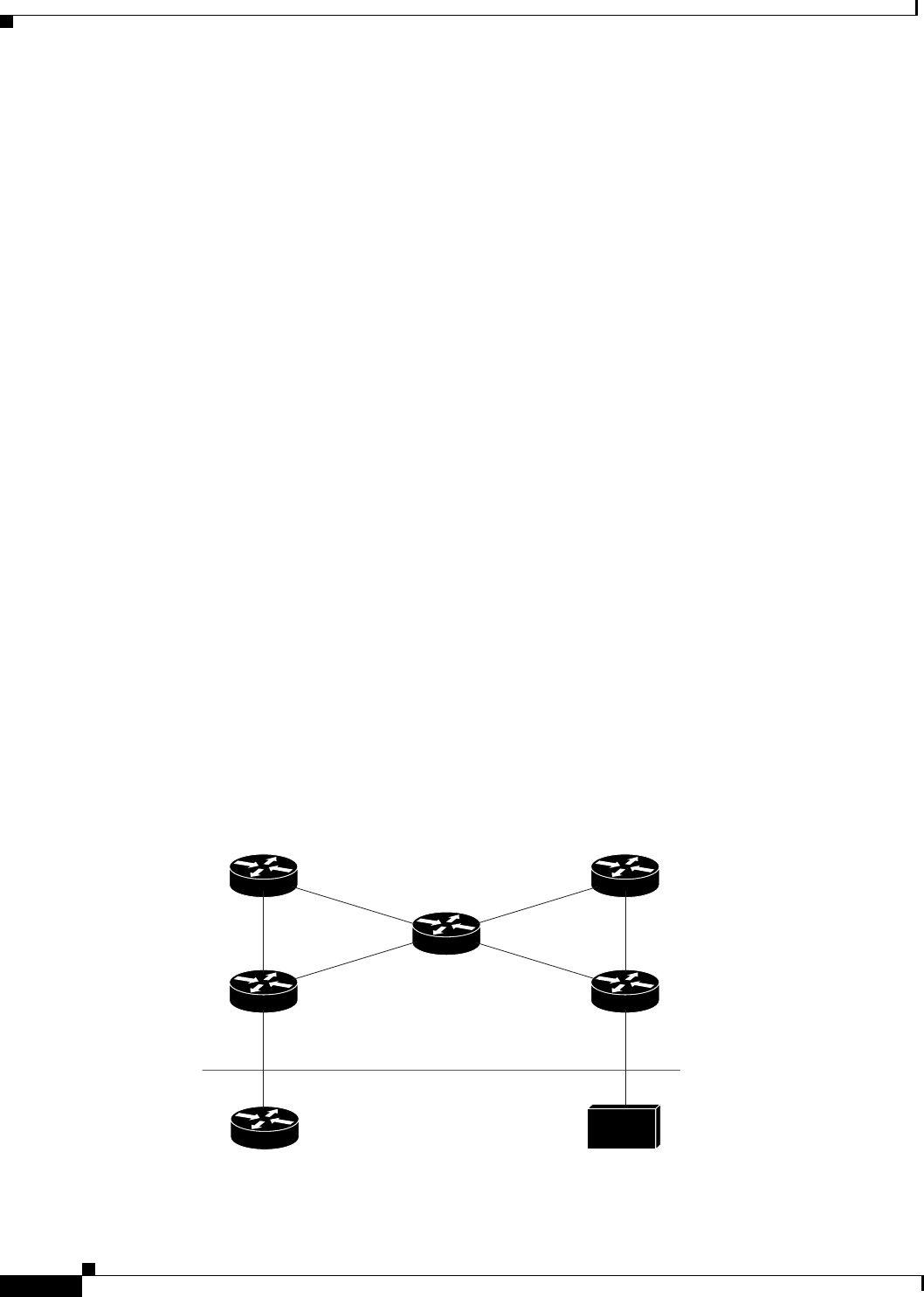
Figure 21 shows two PEs with HSRP running between their VRF interfaces. The CE is configured with
the HSRP virtual IP address as its default route. HSRP is configured to track the interfaces connecting
the PEs to the rest of the provider network. For example, if interface E1 of PE1 fails, the HSRP priority
will be reduced such that PE2 takes over forwarding packets to the HSRP virtual IP address.
Figure 21 Topology Showing HSRP Support Between Two VRF Interfaces
P1
E1 E1
E2 E2
E0
(vrf1)
E0
(vrf1)
E0
CE
PE1
(Active)
10.2.0.20
P2
E0
Host
PE2
(Standby)
10.2.0.20
Default route set to HSRP
virtual IP address (10.2.0.20)
45588