


Configuring Unidirectional Link Routing
UDLR Configuration Examples
IPC-514
Cisco IOS IP Configuration Guide
tunnel udlr receive-only serial 0
!
! Configure OSPF.
!
router ospf <pid>
network 10.0.0.0 0.255.255.255 area 0
Router B Configuration
ip multicast-routing
!
! Serial1 has receive-only capability
!
interface serial 1
encapsulation hdlc
ip address 10.1.0.2 255.255.0.0
ip pim sparse-dense-mode
!
! Configure tunnel as send-only UDLR tunnel.
!
interface tunnel 0
tunnel source 11.0.0.2
tunnel destination 11.0.0.1
tunnel udlr send-only serial 1
tunnel udlr address-resolution
!
! Configure OSPF.
!
router ospf <pid>
network 10.0.0.0 0.255.255.255 area 0
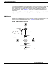
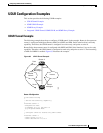
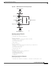
IGMP UDLR Example
The following example shows how to configure IGMP UDLR. In this example, uplink-rtr is the local
upstream router and downlink-rtr is the downstream router. Figure 84 illustrates the example.
Both routers are also connected to each other by a back channel connection. Both routers have two IP
addresses: one on the UDL and one on the interface that leads to the back channel. The back channel is
any return route and can have any number of routers.
Note Configuring PIM on the back channel interfaces on the uplink router and downlink router is optional.
All routers on a UDL must have the same subnet address. If all routers on a UDL cannot have the same
subnet address, the upstream router must be configured with secondary addresses to match all the
subnets that the downstream routers are attached to.