


Configuring Routing Information Protocol
RIP Configuration Task List
IPC-211
Cisco IOS IP Configuration Guide
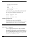
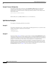
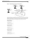
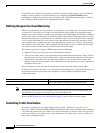
Figure 35 Disabled Split Horizon Example for Frame Relay Network
In this example, split horizon is disabled on all serial interfaces. However, split horizon must be disabled
on Router C in order for network 128.125.0.0 to be advertised into network 131.108.0.0, and vice versa.
These subnets overlap at Router C, interface S0. If split horizon were enabled on serial interface S0, it
would not advertise a route back into the Frame Relay network for either of these networks.
Configuration for Router A
interface ethernet 1
ip address 12.13.50.1
!
interface serial 1
ip address 128.125.1.2
encapsulation frame-relay
no ip split-horizon
Configuration for Router B
interface ethernet 2
ip address 20.155.120.1
!
interface serial 2
ip address 131.108.1.2
encapsulation frame-relay
no ip split-horizon
Configuration for Router C
interface ethernet 0
ip address 10.20.40.1
!
interface serial 0
ip address 128.125.1.1
ip address 131.108.1.1 secondary
encapsulation frame-relay
no ip split-horizon
Router B
Router C
Router A
E1
E0
S1
Interface address:
131.108.1.2
Interface address:
128.125.1.2
Secondary
interface address:
131.108.1.1
Interface address:
128.125.1.1
S0
E2
S2
Network address:
12.13.50.0
Interface address:
12.13.50.1
Network address:
10.20.40.0
Interface address:
10.20.40.1
Network address:
20.155.120.0
Interface address:
20.155.120.1
S1069a
Frame Relay
network
Network
address:
128.125.1.0
Network
address:
131.108.1.0