


Configuring Server Load Balancing
IOS SLB Configuration Task List
IPC-146
Cisco IOS IP Configuration Guide
HSRP uses a priority scheme to determine which HSRP-configured Layer 3 switch is to be the default
active Layer 3 switch. To configure a Layer 3 switch as active, you assign it a priority higher than that
of all other HSRP-configured Layer 3 switches. The default priority is 100, so if you configure just one
Layer 3 switch to have a higher priority, that switch becomes the default active switch.
HSRP works by the exchange of multicast messages that advertise priority among HSRP-configured
Layer 3 switches. When the active switch fails to send a hello message within a configurable period, the
standby switch with the highest priority becomes the active switch. The transition of packet-forwarding
functions between Layer 3 switches is completely transparent to all hosts accessing the network.
HSRP-configured Layer 3 switches exchange the following types of multicast messages:
• Hello—The hello message conveys the HSRP priority and state information of the switch. By
default, an HSRP switch sends hello messages every 3 seconds.
• Coup—When a standby Layer 3 switch assumes the function of the active switch, it sends a coup
message.
• Resign—The active Layer 3 switch sends a resign message when it is about to shut down or when a
switch that has a higher priority sends a hello message.
At any time, HSRP-configured Layer 3 switches are in one of the following states:
• Active—The switch is performing packet-transfer functions.
• Standby—The switch is prepared to assume packet-transfer functions if the active router fails.
• Speaking and listening—The switch is sending and receiving hello messages.
• Listening—The switch is receiving hello messages.
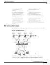
Configuring IOS SLB Stateless Backup
To configure stateless backup, perform the following tasks. The first task is required; the second task is
optional:
• Configure IOS SLB switches to run HSRP between interfaces on the server side
• Configure multiple IOS SLB switches that share a virtual IP address as long as the client ranges are
exclusive and you use policy routing to forward the flows to the correct IOS SLB switch
To configure stateless backup over VLANs between IOS SLB switches, perform the following steps:
Step 1 Configure the server farms. See the “Specifying a Server Farm” section earlier in this chapter.
Step 2 Configure the real servers. See the “Specifying a Real Server” section earlier in this chapter.
Step 3 Configure the virtual servers. See the “Specifying a Virtual Server”section earlier in this chapter.
Note When you use the inservice (virtual service) command to configure the virtual server as
“in-service” you must use the optional standby interface configuration command and
configure an HSRP group name.
Step 4 Configure the IP routing protocol. See the “IP Routing Protocols” part of the Cisco IOS IP Configuration
Guide.
Step 5 Configure the VLAN between the switches. See the “Virtual LANs” chapter of the Cisco IOS
Switching Services Configuration Guide.
Step 6 Enable HSRP. See the “Enabling HSRP” section earlier in this chapter.