


Configuring OSPF
OSPF Configuration Examples
IPC-248
Cisco IOS IP Configuration Guide
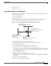
Note It is not necessary to include definitions of all areas in an OSPF autonomous system in the
configuration of all routers in the autonomous system. You must only define the directly connected
areas. In the example that follows, routes in area 0 are learned by the routers in area 1 (Router A and
Router B) when the ABR (Router C) injects summary LSAs into area 1.
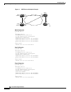
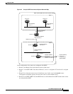
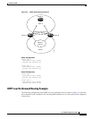
The OSPF domain in BGP autonomous system 109 is connected to the outside world via the BGP link
to the external peer at IP address 11.0.0.6. Example configurations follow.
Following is the sample configuration for the general network map shown in Figure 42.
Router A Configuration—Internal Router
interface ethernet 1
ip address 131.108.1.1 255.255.255.0
router ospf 1
network 131.108.0.0 0.0.255.255 area 1
Router B Configuration—Internal Router
interface ethernet 2
ip address 131.108.1.2 255.255.255.0
router ospf 202
network 131.108.0.0 0.0.255.255 area 1
Router C Configuration—ABR
interface ethernet 3
ip address 131.108.1.3 255.255.255.0
interface serial 0
ip address 131.108.2.3 255.255.255.0
router ospf 999
network 131.108.1.0 0.0.0.255 area 1
network 131.108.2.0 0.0.0.255 area 0
Router D Configuration—Internal Router
interface ethernet 4
ip address 10.0.0.4 255.0.0.0
interface serial 1
ip address 131.108.2.4 255.255.255.0
router ospf 50
network 131.108.2.0 0.0.0.255 area 0
network 10.0.0.0 0.255.255.255 area 0
Router E Configuration—ASBR
interface ethernet 5
ip address 10.0.0.5 255.0.0.0
interface serial 2
ip address 11.0.0.5 255.0.0.0
router ospf 65001
network 10.0.0.0 0.255.255.255 area 0
redistribute bgp 109 metric 1 metric-type 1