


Configuring IP Routing Protocol-Independent Features
IP Routing Protocol-Independent Configuration Examples
IPC-385
Cisco IOS IP Configuration Guide
!
! Ethernet interface 3 is in area 3:
interface ethernet 3
ip address 172.18.10.5 255.255.255.0
!
! Ethernet interface 4 is in area 0:
interface ethernet 4
ip address 172.19.1.1 255.255.255.0
!
! Ethernet interface 5 is in area 0:
interface ethernet 5
ip address 10.1.0.1 255.255.0.0
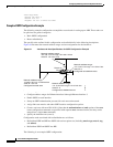
Each network router configuration command is evaluated sequentially, so the specific order of these
commands in the configuration is important. The Cisco IOS software sequentially evaluates the
address/wildcard-mask pair for each interface. See the “IP Routing Protocols Commands” chapter of the
Cisco IOS IP Command Reference, Volume 2 of 3: Routing Protocols publication for more information.
Consider the first network command. Area ID 10.9.50.0 is configured for the interface on which subnet
172.18.20.0 is located. Assume that a match is determined for Ethernet interface 0. Ethernet interface 0
is attached to Area 10.9.50.0 only.
The second network command is evaluated next. For Area 2, the same process is then applied to all
interfaces (except Ethernet interface 0). Assume that a match is determined for Ethernet interface 1.
OSPF is then enabled for that interface and Ethernet 1 is attached to Area 2.
This process of attaching interfaces to OSPF areas continues for all network commands. Note that the
last network command in this example is a special case. With this command, all available interfaces (not
explicitly attached to another area) are attached to Area 0.
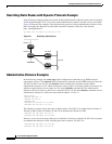
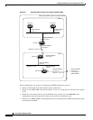
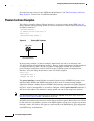
Internal Router, ABR, and ASBRs Configuration Example
Figure 63 provides a general network map that illustrates a sample configuration for several routers
within a single OSPF autonomous system.