


Configuring IGRP
IGRP Configuration Examples
IPC-220
Cisco IOS IP Configuration Guide
IGRP Feasible Successor Relationship Example
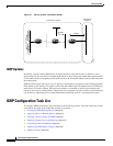
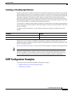
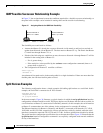
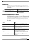
In Figure 37, the assigned metrics meet the conditions required for a feasible successor relationship, so
the paths in this example can be included in routing tables and be used for load balancing.
Figure 37 Assigning Metrics for IGRP Path Feasibility
The feasibility test would work as follows:
• Assume that Router C1 already has a route to Network A with metric m and has just received an
update about Network A from Router C2. The best metric at Router C2 is p. The metric that Router
C1 would use through Router C2 is n.
• If both of the following two conditions are met, the route to Network A through Router C2 will be
included in the routing table of Router C1:
–
If m is greater than p.
–
If the multiplier (value specified by the variance router configuration command) times m is
greater than or equal to n.
• The configuration for Router C1 would be as follows:
router igrp 109
variance 10
A maximum of four paths can be in the routing table for a single destination. If there are more than four
feasible paths, the four best feasible paths are used.
Split Horizon Examples
The following configuration shows a simple example of disabling split horizon on a serial link. In this
example, the serial link is connected to an X.25 network.
interface serial 0
encapsulation x25
no ip split-horizon
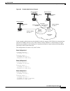
In the next example, Figure 38 illustrates a typical situation in which the no ip split-horizon interface
configuration command would be useful. This figure depicts two IP subnets that are both accessible via
a serial interface on Router C (connected to Frame Relay network). In this example, the serial interface
on Router C accommodates one of the subnets via the assignment of a secondary IP address.
The Ethernet interfaces for Router A, Router B, and Router C (connected to IP networks 12.13.50.0,
10.20.40.0, and 20.155.120.0, respectively) all have split horizon enabled by default, while the serial
interfaces connected to networks 128.125.1.0 and 131.108.1.0 all have split horizon disabled by default.
The partial interface configuration specifications for each router that follow Figure 38 illustrate that the
ip split-horizon interface configuration command is not explicitly configured under normal conditions
for any of the interfaces.
Route to Network A
Metric = m = 10876
Route to Network A
Metric = n = 12776
Route to Network A
Metric = p = 10776
56620
Router C1 Router C2