


89
1745D–ATARM–04-Nov-05
AT91M55800A
14. WD: Watchdog Timer
The AT91M55800A has an internal Watchdog Timer that can be used to prevent system lock-
up if the software becomes trapped in a deadlock.
In normal operation the user reloads the watchdog at regular intervals before the timer over-
flow occurs. If an overflow does occur, the watchdog timer generates one or a combination of
the following signals, depending on the parameters in WD_OMR (Overflow Mode Register):
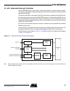
• If RSTEN is set, an internal reset is generated (WD_RESET as shown in Figure 14-1).
• If IRQEN is set, a pulse is generated on the signal WDIRQ which is connected to the
Advanced Interrupt Controller
• If EXTEN is set, a low level is driven on the NWDOVF signal for a duration of 8 MCK cycles.
The watchdog timer has a 16-bit down counter. Bits 12 - 15 of the value loaded when the
watchdog is restarted are programmable using the HPVC parameter in WD_CMR (Clock
Mode). Four clock sources are available to the watchdog counter: MCK/32, MCK/128,
MCK/1024 or MCK/4096. The selection is made using the WDCLKS parameter in WD_CMR.
This provides a programmable time-out period of 4 ms to 8 sec. with a 33 MHz system clock.
All write accesses are protected by control access keys to help prevent corruption of the
watchdog should an error condition occur. To update the contents of the mode and control
registers it is necessary to write the correct bit pattern to the control access key bits at the
same time as the control bits are written (the same write access).
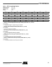
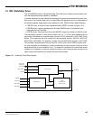
Figure 14-1. Watchdog Timer Block Diagram
Advanced
Peripheral
Bus (APB)
WD_RESET
WDIRQ
MCK/32
MCK/128
MCK/1024
MCK/4096
Control Logic
Clock Select
16-Bit
Programmable
Down Counter
CLK_CNT
Clear
Overflow
NWDOVF