


227
1745D–ATARM–04-Nov-05
AT91M55800A
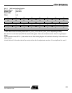
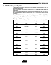
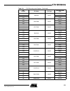
23. JTAG Boundary-scan Register
The Boundary-scan Register (BSR) contains 256 bits which correspond to active pins and
associated control signals.
Each AT91M55800A input pin has a corresponding bit in the Boundary-scan Register for
observability.
Each AT91M55800A output pin has a corresponding 2-bit register in the BSR. The OUTPUT
bit contains data which can be forced on the pad. The CTRL bit can put the pad into high
impedance.
Each AT91M55800A in/out pin corresponds to a 3-bit register in the BSR. The OUTPUT bit
contains data that can be forced on the pad. The INPUT bit is for the observability of data
applied to the pad. The CTRL bit selects the direction of the pad.
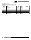
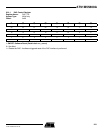
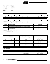
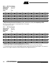
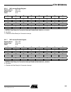
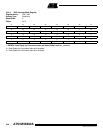
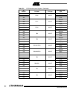
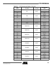
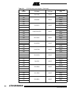
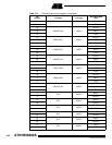
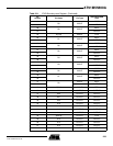
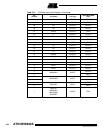
Table 23-1. JTAG Boundary-scan Register
Bit
Number Pin Name Pin Type
Associated BSR
Cells
256 NWAIT INPUT INPUT
255 NRST INPUT INPUT
254
PB18/BMS IN/OUT
OUTPUT
253 INPUT
252 CTRL
251
MCKO OUTPUT
OUTPUT
250 CTRL
249
NWDOVF OUTPUT
OUTPUT
248 CTRL
247
PB17 IN/OUT
OUTPUT
246 INPUT
245 CTRL
244
PB16 IN/OUT
OUTPUT
243 INPUT
242 CTRL
241
PB15 IN/OUT
OUTPUT
240 INPUT
239 CTRL
238
PB14 IN/OUT
OUTPUT
237 INPUT
236 CTRL
235
PB13 IN/OUT
OUTPUT
234 INPUT
233 PB13 IN/OUT CTRL