


206
1745D–ATARM–04-Nov-05
AT91M55800A
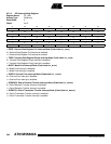
• SCBR: Serial Clock Baud Rate (Code Label SP_SCBR)
In Master Mode, the SPI Interface uses a modulus counter to derive the SPCK baud rate from the SPI Master Clock
(selected between MCK and MCK/32). The Baud rate is selected by writing a value from 2 to 255 in the field SCBR. The
following equation determines the SPCK baud rate:
Giving SCBR a value of zero or one disables the baud rate generator. SPCK is disabled and assumes its inactive state
value. No serial transfers may occur. At reset, baud rate is disabled.
• DLYBS: Delay Before SPCK (Code Label SP_DLYBS)
This field defines the delay from NPCS valid to the first valid SPCK transition.
When DLYBS equals zero, the NPCS valid to SPCK transition is 1/2 the SPCK clock period.
Otherwise, the following equation determines the delay:
NPCS_to_SPCK_Delay = DLYBS * SPI_Master_Clock_period
• DLYBCT: Delay Between Consecutive Transfers (Code Label SP_DLYBCT)
This field defines the delay between two consecutive transfers with the same peripheral without removing the chip select.
The delay is always inserted after each transfer and before removing the chip select if needed.
When DLYBCT equals zero, a delay of four SPI Master Clock periods are inserted.
Otherwise, the following equation determines the delay:
Delay_After_Transfer = 32 * DLYBCT * SPI_Master_Clock_period
SPCK_Baud_Rate =
SPI_Master_Clock_frequency
2 x SCBR