


58
1745D–ATARM–04-Nov-05
AT91M55800A
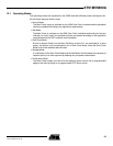
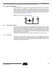
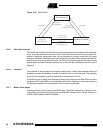
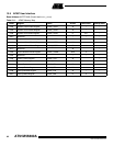
Figure 12-6. Clock Switch
12.3.5 Slow Clock Interrupt
The APMC also features the Slow Clock interrupt, allowing the user to detect when the Master
Clock is actually switched to the Slow Clock. Switching from the Slow Clock to a higher fre-
quency is generally performed safely, as the processor is running slower than the target
frequency. However, switching from a high frequency to the Slow Clock requires the high fre-
quency to be valid during the switch time. The Slow Clock interrupt permits the user to know
exactly when the switch has been achieved, thus, when the Main Oscillator or the PLL can be
disabled.
12.3.6 Prescaler
The prescaler is the last stage to provide the master clock. It permits the selected clock to be
divided by a power of 2 between 1 and 64. The default value is 1 after the reset. The prescaler
allows the microcontroller operating frequency to reach down to 512 Hz.
Precautions must be taken when defining a master clock lower than the Slow Clock, as some
peripherals (RTC and APMC) can still operate at Slow Clock frequency. In this case, access to
the peripheral registers that are updated at 32 kHz cannot be ensured.
12.3.7 Master Clock Output
The Master Clock can be output to the MCKO pad. The MCKO pad can be tri-stated to mini-
mize power consumption by setting the bit MCKODS (Master Clock Output Disable) in
APMC_CGMR (default is MCKO enabled).
Slow Clock Mode
PLL Clock Mode
Oscillator Clock Mode
5 SLCK Cycles
4 SLCK Cycles
+
3 PLL Clock Cycles
5 SLCK Cycles
3 SLCK Cycles
+
3 Oscillator Clock Cycles
5 SLCK Cycles
+
3 PLL Clock Cycles
4 SLCK Cycles
+
3 Oscillator Clock Cycles
7 SLCK Cycles
+
3 PLL Clock Cycles