


29
1745D–ATARM–04-Nov-05
AT91M55800A
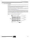
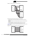
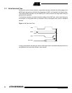
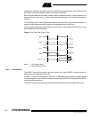
Figure 11-6 shows how to connect a 16-bit device without byte access (e.g. Flash) on NCS2.
Figure 11-6. Connection for a 16-bit Data Bus Without Byte-write Capability.
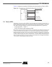
11.5 Boot on NCS0
Depending on the device and the BMS pin level during the reset, the user can select either an
8-bit or 16-bit external memory device connected on NCS0 as the Boot Memory. In this case,
EBI_CSR0 (Chip-select Register 0) is reset at the following configuration for chip select 0:
• 8 wait states (WSE = 1, NWS = 7)
• 8-bit or 16-bit data bus width, depending on BMS
Byte access type and number of data float time are respectively set to Byte-write Access and
0. With a nonvolatile memory interface, any value can be programmed for these parameters.
Before the remap command, the user can modify the chip select 0 configuration, programming
the EBI_CSR0 with exact boot memory characteristics. The base address becomes effective
after the remap command, but the new number of wait states can be changed immediately.
This is useful if a boot sequence needs to be faster.
EBI
D0 - D7
D8 - D15
A1 - A19
NLB
NWE
NOE
NCS2
D0 - D7
D8 - D15
A0 - A18
Write Enable
Output Enable
Memory Enable
NUB