


57
1745D–ATARM–04-Nov-05
AT91M55800A
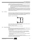
in APMC_SR and loads the PLL counter with the value programmed in the PLLCOUNT field.
Then, the PLL counter decrements at each Slow Clock cycle.
Note: Programming one in PLLCOUNT is the minimum allowed and guarantees at least 2 Slow Clock
cycles before the lock bit is set. Programming n in PLLCOUNT guarantees (n+1) the delay of
Slow Clock cycles. When the PLL Counter reaches 0, the LOCK bit in APMC_SR is set and can
cause an interrupt. Programming MUL or PLLCOUNT before the LOCK bit is set may lead to
unpredictable behavior.
If the PLL multiplication is changed while the PLL is already active, the LOCK bit in APMC_SR
is automatically cleared and the same sequence is restarted. The PLL is automatically
bypassed while the frequency is changing (while LOCK is 0). If the Main Oscillator is reacti
-
vated at the same time the PLL is enabled, the LOCK bit is set only when both the Main
Oscillator and the PLL are stabilized.
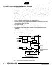
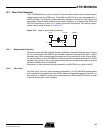
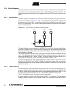
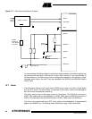
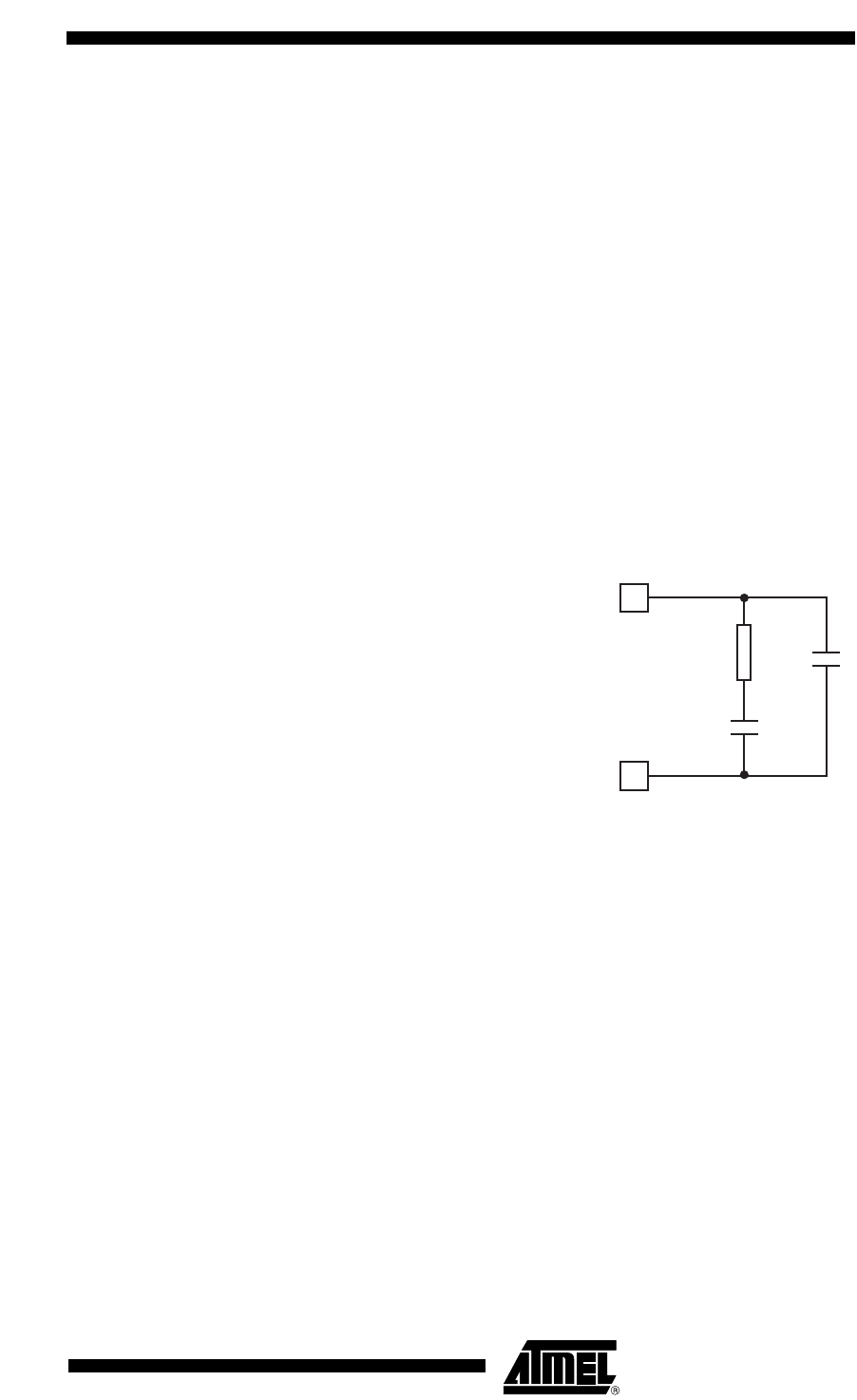
12.3.3 PLL Filter
The Phase Lock Loop has a dedicated PLLRC pin which must connect with an appropriate
second order filter made up of one resistor and two capacitors. If the integrated PLL is not
used, it can remain disabled. The PLLRC pin must be grounded if the resistor and the capaci
-
tors need to be saved. The following figure shows a typical filter connection.
Figure 12-5. Typical Filter Connection
In order to obtain optimal results with a 16 MHz input frequency and a 32 MHz output fre-
quency, the typical component values for the PLL filter are:
R = 287Ω - C1 = 680 nF - C2 = 68 nF
The lock time with these values is about 3.5 µs in this example.
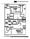
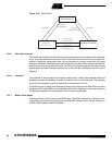
12.3.4 Master Clock Selection
The MCK (Master Clock) can be selected through the CSS field in APMC_CGMR between the
Slow Clock, the output of the Main Oscillator or the output of the PLL.
The following CSS field definitions are forbidden and the write operations are not taken into
account by the APMC:
• deselect the Slow Clock if the Main Oscillator is disabled or its output is not stabilized
• disable the PLL without having first selected the Slow Clock or the Main Oscillator clock
• select the PLL clock and, in the same register, write disable the PLL
• select either the Main Oscillator or the PLL clocks and, in the same register, write disable
the Main Oscillator
• disable the Main Oscillator without having first selected the Slow Clock
This clock switch is performed in some Slow Clocks and PLLs or Main Oscillator clock cycles
as described in the state machine diagram below:
GNDPLL
C
2
C
1
R
PLLRC