


112
1745D–ATARM–04-Nov-05
AT91M55800A
16. PIO: Parallel I/O Controller
The AT91M55800A has 58 programmable I/O lines. 13 pins are dedicated as general-purpose
I/O pins. The other I/O lines are multiplexed with an external signal of a peripheral to optimize
the use of available package pins. The PIO lines are controlled by two separate and identical
PIO Controllers called PIOA and PIOB. The PIO controller enables the generation of an inter-
rupt on input change and insertion of a simple input glitch filter on any of the PIO pins.
16.1 Multiplexed I/O Lines
Some I/O lines are multiplexed with an I/O signal of a peripheral. After reset, the pin is con-
trolled by the PIO Controller and is in input mode.
When a peripheral signal is not used in an application, the corresponding pin can be used as a
parallel I/O. Each parallel I/O line is bi-directional, whether the peripheral defines the signal as
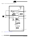
input or output. Figure 16-1 shows the multiplexing of the peripheral signals with Parallel I/O
signals.
If a pin is multiplexed between the PIO Controller and a peripheral, the pin is controlled by the
registers PIO_PER (PIO Enable) and PIO_PDR (PIO Disable). The register PIO_PSR (PIO
Status) indicates whether the pin is controlled by the corresponding peripheral or by the PIO
Controller.
If a pin is a general multi-purpose parallel I/O pin (not multiplexed with a peripheral), PIO_PER
and PIO_PDR have no effect and PIO_PSR returns 1 for the bits corresponding to these pins.
When the PIO is selected, the peripheral input line is connected to zero.
16.2 Output Selection
The user can enable each individual I/O signal as an output with the registers PIO_OER (Out-
put Enable) and PIO_ODR (Output Disable). The output status of the I/O signals can be read
in the register PIO_OSR (Output Status). The direction defined has effect only if the pin is con-
figured to be controlled by the PIO Controller.
16.3 I/O Levels
Each pin can be configured to be driven high or low. The level is defined in four different ways,
according to the following conditions.
If a pin is controlled by the PIO Controller and is defined as an output (see Output Selection
above), the level is programmed using the registers PIO_SODR (Set Output Data) and
PIO_CODR (Clear Output Data). In this case, the programmed value can be read in
PIO_ODSR (Output Data Status).
If a pin is controlled by the PIO Controller and is not defined as an output, the level is deter-
mined by the external circuit.
If a pin is not controlled by the PIO Controller, the state of the pin is defined by the peripheral
(see peripheral datasheets).
In all cases, the level on the pin can be read in the register PIO_PDSR (Pin Data Status).
16.4 Filters
Optional input glitch filtering is available on each pin and is controlled by the registers
PIO_IFER (Input Filter Enable) and PIO_IFDR (Input Filter Disable). The input glitch filtering