


59
1745D–ATARM–04-Nov-05
AT91M55800A
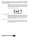
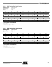
12.4 System Clock
The AT91M55800A has only one system clock: the ARM Core clock. It can be enabled and
disabled by writing to the System Clock Enable (APMC_SCER) and System Clock Disable
Registers (APMC_SCDR). The status of the ARM Core clock (at least for debug purposes)
can be read in the System Clock Status Register (APMC_SCSR).
The ARM Core clock is enabled after a reset and is automatically re-enabled by any enabled
interrupt.
When the ARM Core clock is disabled, the current instruction is finished before the clock is
stopped.
Note: Stopping the ARM Core does not prevent PDC transfers.
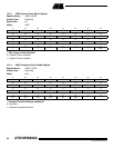
12.5 Peripheral Clocks
Each peripheral clock integrated in the AT91M55800A can be individually enabled and dis-
abled by writing to the Peripheral Clock Enable (APMC_PCER) and Peripheral Clock Disable
(APMC_PCDR) Registers. The status of the peripheral clocks can be read in the Peripheral
Clock Status Register (APMC_PCSR).
When a peripheral clock is disabled, the clock is immediately stopped. When the clock is re-
enabled, the peripheral resumes action where it left off.
In order to stop a peripheral, it is recommended that the system software waits until the periph-
eral has executed its last programmed operation before disabling the clock. This is to avoid
data corruption or erroneous behavior of the system.
The peripheral clocks are automatically disabled after a reset.
The bits that control the peripheral clocks are the same as those that control the Interrupt
Sources in the AIC.
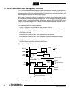
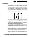
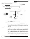
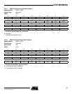
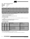
12.6 Shut-down and Wake-up
The APMC (Advanced Power Management Controller) integrates shut-down and wake-up
logic to control an external main power supply. This logic is supplied by the Battery Backup
Power. This feature makes the Power-down mode possible.
If the SHDN pin is connected to the shut-down pin of the main power supply, the Shut-down
command (SHDALC) in APMC_PCR disables the main power. The shut-down input of the
converter is generally pulled up or down by a resistor, depending on its active level.
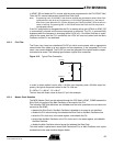
There are 3 ways to exit Power-down mode and restart the main power:
• An alarm programmed in the RTC occurs and the bit ALWKEN in APMC_PMR is set.
• An edge defined by the field WKEDG in APMC_PMR occurs on the pin WAKEUP.
• The user opens the Shut-down line with an external jumper or push-button.
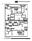
Figure 12-7 shows a typical application using the Shut-down and Wake-up features.